EPSON | Chapter 4 Disassembly and Assembly |
|
|
|
|
|
| 4.2.11.9 Removing the CR Assembly | |
IMPORTANT |
|
|
|
|
|
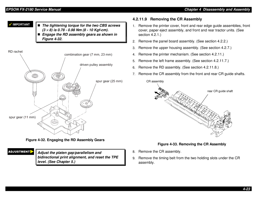
| The tightening torque for the two CBS screws |
| 1. | Remove the printer cover, front and rear edge guide assemblies, front | |
|
| T(3 × 8) is 0.78 - 0.98 Nm (8 - 10 |
|
| cover, paper eject assembly, and front and rear tractor units. (See |
|
| Engage the RD assembly gears as shown in |
|
| section 4.2.1.) |
|
| Figure |
| 2. | Remove the panel board assembly. (See section 4.2.2.) |
|
|
|
| ||
|
|
|
| ||
|
|
| 3. | Remove the upper housing assembly. (See section 4.2.7.) | |
R D r a c h e t | g e a4. rRemove( 7the mprinterm mechanism, 2 3 . (Seem msection) 4.2.11.) | ||||
|
| c o m b in a t io n | |||
|
|
| 5. | Remove the left frame assembly. (See section 4.2.11.7.) | |
|
| d r iv e n p u lle y | a s s e m b ly | ||
|
|
| 6. | Remove the RD assembly. (See section 4.2.11.8.) | |
|
|
| 7. | Remove the CR assembly from the front and rear CR guide shafts. | |
s p u r g e a r (CR2 assembly5 m m )
rear CR guide shaft
s p u r g e a r ![]()
![]() ( 1 1
( 1 1![]()
![]() m
m![]() m )
m )
Figure 4-32. Engaging the RD Assembly Gears
Adjust the platen gap/parallelism and bidirectional print alignment, and reset the TPE level. (See Chapter 5.)
Figure 4-33. Removing the CR Assembly
8.Remove the CR assembly.
9.Remove the timing belt from the two holding slots under the CR assembly.