EPSON | Chapter 4 Disassembly and Assembly |
|
|
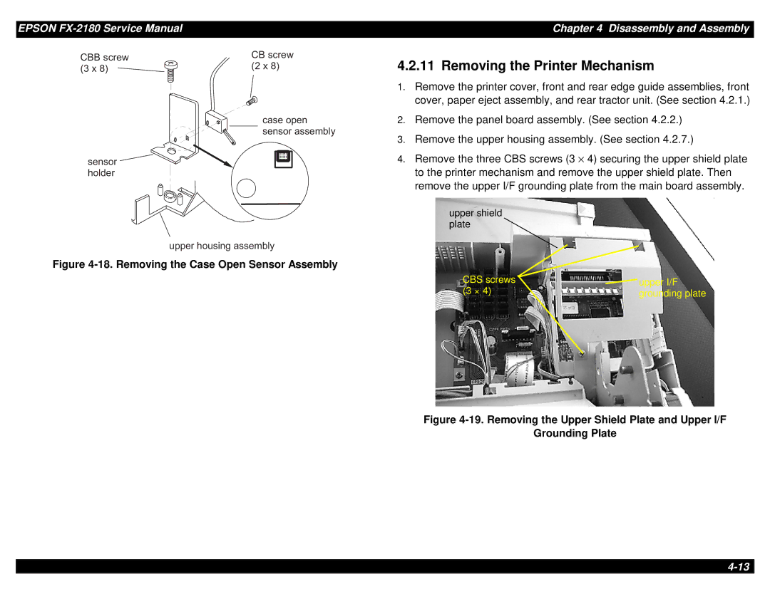
C B B s c r e w ( 3 x 8 )
C B | s c r e w | 4.2.11 Removing the Printer Mechanism |
( 2 | x 8 ) | |
|
| 1. Remove the printer cover, front and rear edge guide assemblies, front |
|
| cover, paper eject assembly, and rear tractor unit. (See section 4.2.1.) |
s e n s o r h o l d e r
c a s e o p e n 2. Remove the panel board assembly. (See section 4.2.2.) s e n s o r a s s e m b ly
3.Remove the upper housing assembly. (See section 4.2.7.)
4. Remove the three CBS screws (3 × 4) securing the upper shield plate to the printer mechanism and remove the upper shield plate. Then remove the upper I/F grounding plate from the main board assembly.
upper shield plate
u p p e r h o u s in g a s s e m b ly
Figure 4-18. Removing the Case Open Sensor Assembly
CBS screws | upper I/F |
(3 × 4) | grounding plate |