EPSON
3.5 Repairing the Main Board Assembly
The table below provides instructions on how to repair the main board assembly. It lists various main board problems and provides likely causes, checkpoints, and solutions. To determine whether a component is defective, compare its readings with the correct waveforms, resistances, and other values listed in the table below. Then replace the component if necessary.
Note:
Use an oscilloscope to check the waveforms in Table
Table
Problem |
| Cause |
| Checkpoint |
| Solution |
|
|
|
|
|
| Chapter 3 Troubleshooting | |||
| Table | ||||||||
|
|
|
|
|
|
|
|
|
|
| Problem |
|
| Cause |
| Checkpoint |
| Solution |
|
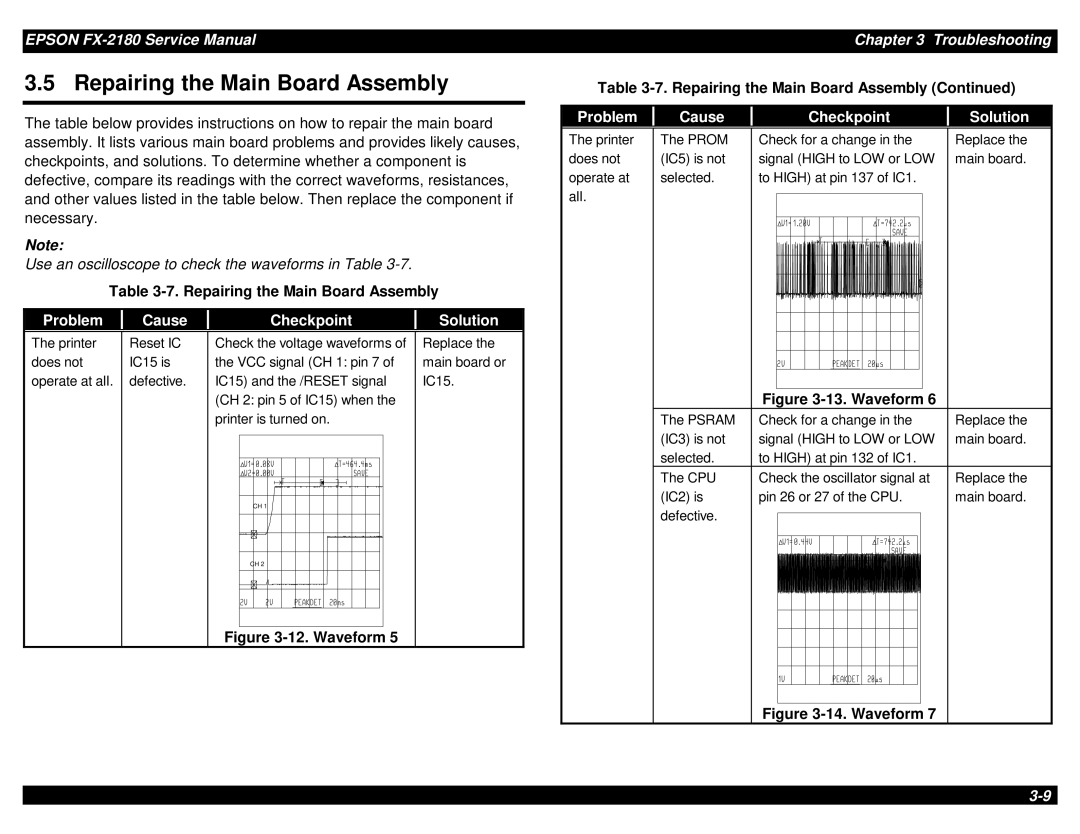
The printer | The PROM | Check for a change in the | Replace the |
does not | (IC5) is not | signal (HIGH to LOW or LOW | main board. |
operate at | selected. | to HIGH) at pin 137 of IC1. |
|
all. |
|
|
|
The printer | Reset IC |
does not | IC15 is |
operate at all. | defective. |
|
|
Check the voltage waveforms of the VCC signal (CH 1: pin 7 of IC15) and the /RESET signal (CH 2: pin 5 of IC15) when the printer is turned on.
CH 1 |
CH 2 |
Figure |
Replace the main board or IC15.
Figure |
The PSRAM | Check for a change in the | Replace the |
(IC3) is not | signal (HIGH to LOW or LOW | main board. |
selected. | to HIGH) at pin 132 of IC1. |
|
The CPU | Check the oscillator signal at | Replace the |
(IC2) is | pin 26 or 27 of the CPU. | main board. |
defective.