EPSON
Chapter 4 Disassembly and Assembly
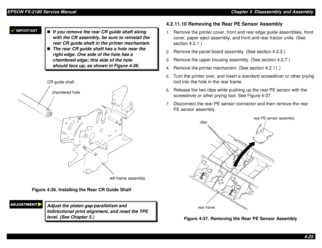
4.2.11.10 Removing the Rear PE Sensor Assembly
IMPORTANT
If you remove the rear CR guide shaft along with the CR assembly, be sure to reinstall the
Trear CR guide shaft in the printer mechanism. The rear CR guide shaft has a hole near the right edge. One side of the hole has a chamfered edge; this side of the hole should face up, as shown in Figure
1. | Remove the printer cover, front and rear edge guide assemblies, front |
| cover, paper eject assembly, and front and rear tractor units. (See |
| section 4.2.1.) |
2. | Remove the panel board assembly. (See section 4.2.2.) |
3. | Remove the upper housing assembly. (See section 4.2.7.) |
4. | Remove the printer mechanism. (See section 4.2.11.) |
5. | Turn the printer over, and insert a standard screwdriver or other prying |
CR guide shaft
chamfered hole
left frame assembly
Figure 4-36. Installing the Rear CR Guide Shaft
Adjust the platen gap/parallelism and bidirectional print alignment, and reset the TPE level. (See Chapter 5.)
| tool into the hole in the rear frame. |
6. | Release the two clips while pushing up the rear PE sensor with the |
| screwdriver or other prying tool. See Figure |
7. | Disconnect the rear PE sensor connector and then remove the rear |
| PE sensor assembly. |
rear PE sensor assembly
clips
rear frame