Manuals
/
EverFocus
/
TV and Video
/
DVR
EverFocus
ECOR264-4F1, ECOR264-8F1 user manual Install the ePlusDVR.cab file when prompted to do so
Models:
ECOR264-4D1
ECOR264-8D1
1
107
128
128
Download
128 pages
15.06 Kb
104
105
106
107
108
109
110
111
<
>
Troubleshooting
Specifications
Install
Operation in the Configuration Menus
RS-485 bus serial wiring with connector boxes and connection cable
Alarm Reset Input Event Alarm Duration
MENUPress this key to enter/exit MAIN SETUP MENU
Type “command” and click on OK
Connection Procedure
The default port for the ECOR264-4/ECOR264-8 is
Page 107
Image 107
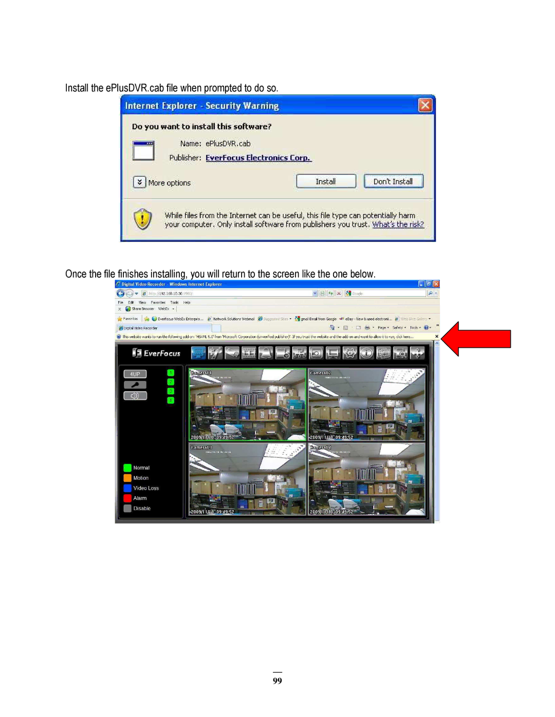
Install the ePlusDVR.cab file when prompted to do so.
Once the file finishes installing, you will return to the screen like the one below.
99
Page 106
Page 108
Page 107
Image 107
Page 106
Page 108
Contents
User Manual
ECOR264-4F1/ECOR264-4D1 ECOR264-8F1/ECOR264-8D1
Release Date Nov
ECOR264-4F1/ ECOR264-4D1 ECOR264-8F1/ ECOR264-8D1 Instruction Manual
Retain Instructions
Safety Precautions
Cleaning
Read Instructions
Servicing
Power Cord Protection
Attachments
Water and Moisture
WEEE
GENERAL DVR OPERATIONS
TABLE OF CONTENTS
2 MOUSE AND FRONT PANEL OPERATION
DVR CONFIGURATION
General PTZ control if PTZ cameras are installed
6 REMOTE OPERATION FROM BROWSER
Chapter
1.1 FEATURES
1 PRODUCT OVERVIEW
Mouse x
1.2 PACKAGE CONTENTS
Digital Video Recorder User Manual x AC Adapter and Power Cord
1.3 SPECIFICATIONS
Note2 9-screen display available in 8 Channel model only
1.4 FRONT PANEL
Note1 PIP display is not available in playback mode
7 / I IReverse playback or pause 8 / I IForward playback or pause
11 POWER LED This LED ON indicates Power on
12 ALARM LED This LED ON indicates Alarm active
19 MENUPress this key to enter/exit MAIN SETUP MENU
1.5 REAR PANEL
1.7 AUDIO INSTALLATION
1.6 VIDEO INPUTS/OUTPUTS INSTALLATION
1.8 ALARM CONTACTS INSTALLATION
1.9.1 General RS-485 bus installation
1.9 RS-485 keyboard / PTZ Installation
1.8.1 Alarm Input Contacts
1.8.2 Alarm Output Relay
Star wiring with RS-485 signal distributor
RS-485 bus serial wiring with connector boxes and connection cable
Improper RS-485 bus star wiring
1.9.4 EKB-500 connection to several DVRs
1.9.5 Speed Dome Installation
1.9.2 RS-485 socket pin assignment
1.9.3 EKB-500 connection with network patch cable
1.11.1 Direct PC Connection through Crossover Network Cable
1.10USB-Mouse installation
1.11NETWORK CONNECTION
1.11.2 Network Connection through Patch Cable
1.12FINAL INSTALL PROCESS
2.1 GENERAL USB MOUSE OPERATION
2.1.1 How to select a channel / Enable audio
2.1.3 Operation in the Configuration Menus
2 MOUSE AND FRONT PANEL OPERATION
2.1.4 Field Input Options
Bar Click and hold on the bar to adjust the set point Left or Right
2.2.2 OSD Root Menu
2.2.1 How to select a channel / Enable audio
2.2.4 Operation in Configuration Menu
2.2 General Front Panel Operation
2.2.5 Field Input Options
The buttons on the right and bottom have the following functions
Chapter
3.2 LOGIN
3. GENERAL DVR OPERATIONS
3.1 RECORD
Figure 3-2 On-screen Keyboard
3.3 SELECT CAMERA OPERATION
3.4 CHANGE AUDIO OUTPUT OPERATION
3.5 PLAYBACK
2009/05/25 091030PM
2009/05/25 090930PM
2009/05/25 090940PM
3.6.1 General PTZ control if PTZ cameras are installed
3.6 PTZ
Figure 3-3 Express Control PTZ
3.6.2 Express Control of PTZ
∙ 6 Focus closer ∙ 10 Focus further ∙ 7 Zoom in ∙ 11 Zoom out
REMEMBER
∙ 14, 15 PTZ tilt down ∙ 16 PTZ pan/tilt right and down
3.7.1 Bring to full screen mode
3.8 CHANNEL SWITCHING
3.7 LAYOUT
HD temp. too high
3.9 DISPLAY
3.10 SEQUENCE
3.11 ZOOM
Figure 3-4 Zoom Express Control
3.12 SEARCH
Figure 3-5 Search Menu - Time Search
3.12.1 Time Search
Camera Select which cameras to search for
3.12.2 Event Search
From Select starting date and time To Select ending date and time
3.13 COPY
3.14 LOGOUT
Chapter
4 DVR CONFIGURATION
4.1 CONFIGURATION MENU
4.2 EXPRESS
Record With
Record Mode
Network Type
correctly if you plan to use the DDNS feature see Section
4.3.1 Basic Setting
4.3 CAMERA SETTING
Page
4.3.2 Video Adjust
4.3.3 Motion
How to select motion grid by mouse 1. Select lower-right grid
Output Type Output action when motion is triggered
Timeout Alarm output lasts for the set time duration
Timeout Duration Time duration selectable from 1 to 150 seconds
Figure 4-5 Camera Menu - Motion Grid Setting
Figure 4-6 Camera Menu - Video Loss
4.3.4 Video Loss
4.4.1 Record
4.4 RECORD & PLAY SETTING
4.4.2 Built-in Calculator
4.4.3 Play
xx days of data can be stored based on current setting
4.5.1 Alarm
4.5 ALARM & EVENT SETTING
Timeout Duration Time duration selectable from 1 to 150 seconds
Output Type Output action when alarm is triggered
Timeout Alarm output lasts for the set time duration
Transparent Alarm output remains as long as the alarm input is active
4.5.2 Event
HD Temperature
Figure 4-13 Alarm & Event Menu - Event - HD Failure
HD Failure
Figure 4-14 Alarm & Event Menu - Event - HD Full
HD Full
Figure 4-15 Alarm & Event Menu - Event - HD Off
HD Off
Figure 4-16 Alarm & Event Menu - Event - Power Loss
Power Loss
Figure 4-17 Alarm & Event Menu - Event - Network Loss
Network Loss
4.5.4 Express Setup
4.5.3 Schedule Setting
4.5.5 Holidays
4.5.6 Schedule
To Set Schedule using Mouse
Schedule Setting from front panel
Page
Editing Timezone
NTSC 720x480 720x240 PAL 720x576 / 720x288
To Set Schedule using Mouse
4.5.7 Alarm Action
Alarm Action Setting from front panel
Page
Page
Network Type
4.6 NETWORK SETTING
4.6.1 LAN
Additional information
The default port for the ECOR264-4/ECOR264-8 is
HTTP Port Port number for HTTP/WEB communication
4.6.2 EMAIL
NOTE For more reliable email service, use the server’s IP address
EverfocusDDNS
4.6.3 DDNS
User name User name of the dyndns account
Password Password of the dyndns account Confirm Re-enter password
Example http//hostname.everfocusddns.com
Host name Host name created through the dyndns account
4.6.4 Alarm Server
4.7.1 Disk
4.7 Disk Information
Main Monitor
4.8 DISPLAY SETTING
4.8.1 Monitor OSD
Camera Select which camera appears in the current step
4.8.2 Main M/T SEQ
Step Sequence order. For reference
4.9.1 Date/Time
4.9 SYSTEM SETTING
4.9.2 Daylight Saving
4.9.3 User
Figure 4-34 System Menu - User - Edit
Edit
User Level and Right
Configuration Menu at the DVR
Main Menu at the DVR
User Level and Right
Control
4.9.4 I/O Control
RS485
Everfocus, or Samsung. NOTE all cameras must use the same protocol
Firmware
Configurations
4.9.5 Misc
Network
4.10 INFORMATION
4.10.1 System
System
Log Type
4.10.2 Log
From
Figure 4-39 Log List
Prev Page Go to the previous page of log
Next Page Go to the next page of log Close Close the window
5.3 Gateway Address
5 Networking Overview
5.1 Introduction to TCP/IP
5.2 Subnet Masks
5.4 Virtual Ports
5.5 Pre-Installation
5.6 What is your Network Setup?
Crossover Ethernet Cable Pin outs
5.7 Simple One to One Connection
Connection Procedure
Page
Page
Restart both the computer and the DVR
Click on the option that says “Use the following IP address”
Connection Procedure
5.8 Direct High Speed Modem Connection
Straight Through Ethernet Cable Pin outs
Note If you have a dynamic IP address, you can set the DVR to DHCP to automatically detect the network settings. Therefore, it can use a dynamic IP address
Straight Through Ethernet Cable Pin outs
5.9 Router or LAN Connection
Connection Procedure
Type “command” and click on OK
Log into the EverFocus DVR menu and go to the Network Setting Menu
Exit from the Menu to save settings To manually assign an address
o If using Windows Vista, choose Search instead
To set DVR for Internet Connection through router
Chapter
6.1 CONNECTING TO ECOR264-4/ECOR264-8
6 REMOTE OPERATION FROM BROWSER
6.2.1 Installing ActiveX controls
6.2 BROWSER SECURITY SETTING
Install the ePlusDVR.cab file when prompted to do so
Now, you will able to see the remote live page
Install the MSXML file when prompted to do so
Right click on the yellow bar and select “Run Add-on…”
6.2.2 Enabling ActiveX Controls
“Prompt”
“Enable”
Click the Refresh button to reload the page
Close the window so you are back at the login screen
Install the ePlusDVR.cab file when prompted to do so
Default password
6.3 REMOTE LIVE VIEW
6.4 REMOTE PLAYBACK
Chapter
7 EVERFOCUS DDNS SETUP
DDNS name until you get “Success”
Chapter
8 LINKSYS & D-LINK PORT FORWARDING
8.2 TYPICAL LINKSYS PORT FORWARDING
Here is an example for how the port information might look
8.3 TYPICAL D-LINK PORT FORWARDING
Virtual Server - Select Enabled or Disabled
Schedule
There is no display coming from one of the channels on the DVR
9 TROUBLESHOOTING
The DVR will not go into record mode
The DVR displays nothing on the main monitor
Appendix
APPENDIX A TIMING OF ALARM MODES
t Duration = t Reaction
Alarm Reset Input Event Alarm Duration
t Event
Timeout Mode Retrigger of Alarms
APPENDIX B EXPRESS SETUP RECORDING VALUE SELECTION RULES
Case
Record Mode Normal + Event
Record With Recording days
Preset Setting Option
Record With Preset Setting
Case Record Mode Normal + Event or Event Only
Appendix
APPENDIX C REMOTE CONTROL
Japan Office
Headquarter Office
Beijing office
European Office