Manuals
/
EverFocus
/
TV and Video
/
DVR
EverFocus
ECOR264-4D1, ECOR264-8F1, ECOR264-8D1, ECOR264-4F1
user manual
Models:
ECOR264-4F1
ECOR264-8F1
ECOR264-4D1
ECOR264-8D1
1
98
128
128
Download
128 pages
15.06 Kb
95
96
97
98
99
100
101
102
Specifications
Install
Alarm Input Contacts
Login
Configuration Menu
Express Setup
Timeout Mode
Connection Procedure
Video Adjust
Camera Setting
Page 98
Image 98
90
Page 97
Page 99
Page 98
Image 98
Page 97
Page 99
Contents
ECOR264-4F1/ECOR264-4D1 ECOR264-8F1/ECOR264-8D1
ECOR264-4F1/ ECOR264-4D1 ECOR264-8F1/ ECOR264-8D1
Read Instructions
Safety Precautions
Cleaning
Retain Instructions
Water and Moisture
Power Cord Protection
Attachments
Servicing
Weee
Table of Contents
General PTZ control if PTZ cameras are installed
Information
Vii
Features
Product Overview
Package Contents
Specifications
Sata
Front Panel
Front Panel
Page
Rear Panel
Rear Panel
Video INPUTS/OUTPUTS Installation
Alarm Contacts Installation
Alarm Output Relay
RS-485 keyboard / PTZ Installation
Alarm Input Contacts
General RS-485 bus installation
Improper RS-485 bus star wiring
EKB-500 connection with network patch cable
Speed Dome Installation
2 RS-485 socket pin assignment
EKB-500 connection to several DVRs
Direct PC Connection through Crossover Network Cable
10USB-Mouse installation
11NETWORK Connection
12FINAL Install Process
Network Connection through Patch Cable
General USB Mouse Operation
How to select a channel / Enable audio
Operation in the Configuration Menus
OSD Root Menu
Field Input Options
OSD Menu
Page
Front Panel Key Review
Operation in Configuration Menu
General Front Panel Operation
Field Input Options
Page
Login
Record
Playback
Select Camera Operation
Change Audio Output Operation
2009/05/25 090930PM 2009/05/25 090940PM 2009/05/25 091030PM
PTZ
Express Control of PTZ
Express Control PTZ
Remember
Layout
Channel Switching
Bring to full screen mode
Zoom
Display
Sequence
Search
Zoom Express Control
Time Search
Search Menu Time Search
Event Search
Search Menu Event Search
Copy
Copy Menu
Logout
Logout Confirmation window
Configuration Menu
Express
Record Mode
Record With
Correctly if you plan to use the Ddns feature see Section
Network Type
Camera Setting
Basic Setting
Page
Video Adjust
Camera Menu Video Adjust
Motion
Camera Menu Motion
Page
Camera Menu Motion Grid Setting
Video Loss
Camera Menu Video Loss
Record & Play Setting
Record
Built-in Calculator
Record & Play Menu-Built-in Cal
Xx days of data can be stored based on current setting
Play
Alarm & Event Setting
Alarm
Page
11 Alarm & Event Menu Event
Event
HD Temperature
12 Alarm & Event Menu Event HD Temperature
13 Alarm & Event Menu Event HD Failure
HD Failure
14 Alarm & Event Menu Event HD Full
HD Full
15 Alarm & Event Menu Event HD Off
HD Off
Power Loss
16 Alarm & Event Menu Event Power Loss
17 Alarm & Event Menu Event Network Loss
Network Loss
Schedule Setting
Express Setup
Holidays
19 Schedule Menu-Holidays
To Set Schedule using Mouse
Schedule
Schedule Setting from front panel
Page
Editing Timezone
21 Schedule Menu-Schedule-Edit Timezone
Page
Alarm Action
Alarm Action Setting from front panel
Page
Page
Network Setting
1 LAN
Page
23 Network Menu Email
Ddns
EverfocusDDNS
Page
Alarm Server
26 Network Menu Alarm Server
Disk Information
Disk
Main Monitor
Display Setting
Monitor OSD
Main M/T SEQ
29 Display Menu Main M/T SEQ
System Setting
Date/Time
Daylight Saving
31 System Menu Daylight Saving
User
Add
Edit
34 System Menu User Edit
Configuration Menu at the DVR
Main Menu at the DVR
Control
4 I/O Control
RS485
Firmware
Configurations
Misc
System
Information
System
Network
Log Type
10.2 Log
From
39 Log List
Gateway Address
Introduction to TCP/IP
Subnet Masks
Pre-Installation
Virtual Ports
What is your Network Setup?
Simple One to One Connection
Crossover Ethernet Cable Pin outs
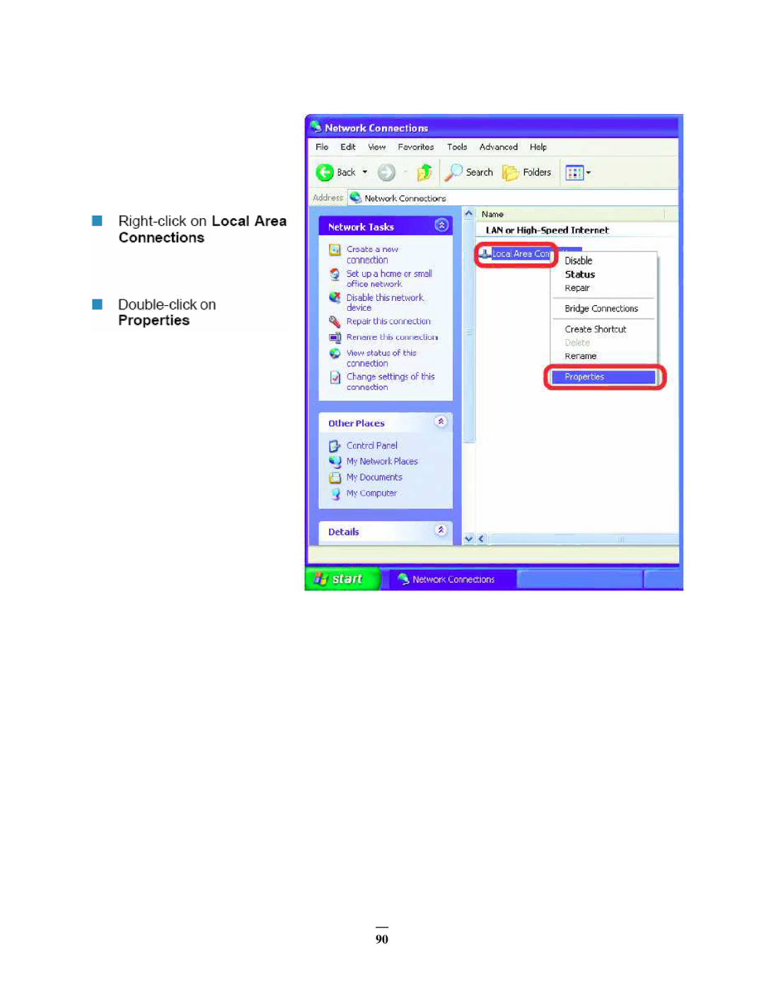
Connection Procedure
Page
Page
Page
Direct High Speed Modem Connection
Straight Through Ethernet Cable Pin outs
Page
Router or LAN Connection
Page
To set DVR for Internet Connection through router
Connecting to ECOR264-4/ECOR264-8
Remote Operation from Browser
Browser Security Setting
Installing ActiveX controls
Page
100
Enabling ActiveX Controls
Enable
Prompt
103
Remote Live View
Remote Playback
Everfocus Ddns Setup
Ddns name until you get Success
Linksys & D-LINK Port Forwarding
Typical Linksys Port Forwarding
Http
Typical D-LINK Port Forwarding
Virtual Server Select Enabled or Disabled
Schedule
Cannot connect to the recorder via the internet
DVR will not go into record mode
DVR displays nothing on the main monitor
Appendix a Timing of Alarm Modes
Timeout Mode
116
Appendix B Express Setup Recording Value Selection Rules
118
Appendix C Remote Control
MELRG00710
Top
Page
Image
Contents