AVT 200HD
Safety Instructions English
FCC Class a Notice
Conventions Used in this Guide
Contents
Html Configuration
About the AVT 200HD Tuner
Features
About this Guide
AVT 200HD Tuner Introduction
Application Diagram for the AVT 200HD
Application Diagram
Installation Overview
Installation
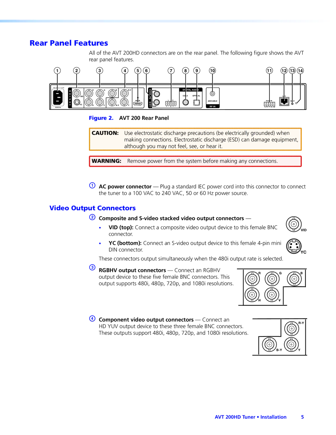
Composite and S-video stacked video output connectors
Rear Panel Features
Video Output Connectors
Analog audio output connectors
Audio Output Connectors
Digital audio output connectors
Input Connector
Remote Configuration and Control Connectors
Ethernet Connection
Wiring for RS-232 Control
Control Connections
Wiring the IR Link
Wiring for IR Control
Connecting the AVT 200HD to the IR Link
Connecting to the USB Port
Found New Hardware Wizard Opening Screen
AVT 200HD Tuner Installation
AVT 200HD Front Panel
Front Panel Features
NBC-4LA
Hdcp Compliance
Power-up and Default Cycle Screens Example
Powering On
Menu System Overview
Using the menus
Menus on the LCD Screen
AVT 200HD Menu Flow
Menu flow diagram
Option Scans for
Channel Setup Menu
Selecting the signal source
Scanning for channels
Scanning
Cable
Channels with long minor numbers
Selecting tune or preset mode
Output Configuration Menu
Selecting a channel
Saving presets Not available via the front panel
Selecting the output resolution and refresh rate
Recalling presets
Simultaneous Video Output
Selecting the display mode
Resolution Composite
Selecting the display aspect ratio
Selecting the closed caption service
Audio Configuration Menu
Comm Setting Menu Flow
Comm Setting Menus
Configuring the serial port and IP parameters
Viewing serial port and IP settings
Unit Reset Menu Flow
Unit Reset Menu Resetting from the Front Panel
Exiting the Menu System
Volume Control
Resetting from the Rear Panel
Reset Modes Summary Activation Result Purpose/Notes
Locking and Unlocking the Front Panel Executive Modes
Exec Mode Select Disable
Executive Mode Menu Flow
Using the AVT 200HD IR Remote Control
Area for Remote Signal Reception
Installing batteries in the AVT 100 Remote
Buttons on the AVT 200 Remote Control
Buttons on the AVT 200HD Remote Control
Channel Selection buttons 0 through
Selecting a Channel or Preset Using the IR Remote Control
Introductory Display
Using the On-screen Display OSD
Locking IR Remote Control Access
Channel Information Display
Volume Level Display
Program Guide
Ethernet Cable
Serial Port
USB Port
Ethernet Port
Establishing an Ethernet Connection
Connection Timeouts
IP Address
Copyright message With an RS-232 connection
Using SIS Commands
Tuner-initiated Messages
Chip Security for Parental Control
Using the Command/Response Tables for SIS Commands
Tuner Error Responses
Error Response References
X1#
Symbol Definitions for AVT 200HD Specific Commands
Special Characters
X1@
X3@ X3#
X2@ X2# X2%
EX!*X@TVSL
Command/Response Table for AVT 200HD SIS Commands
X2%TVPR
EX!*X@TVCH
X!*X@TVCH
EX2&OPOL
EX2%NG
EX2RATE
EX1TVPG
EX1TVTM
EX1TVOS
X1 Fscc
X1 Tvcc
X1% Fscc
X1%
Exafmt
X1&FSCC
X1*FSCC
X2*FSCC
X3@
Chip Setup Parental Control
EX* Lang
X1$ VolX1$
X2@
Chip Setup
X3@*X1VCHP
X3@*X2@VCHP
Tvst ‘‘‘‘‘‘‘‘‘‘‘‘‘‘‘‘‘‘‘‘‘‘‘
Other Settings
$ Tvst
Information Requests
Executive Mode Front Panel Lockout
EZI
Resets
X5# X5$
Symbol Definitions for IP-specific Commands
X4#
X7$
X6#
X6$
X7#
X8$
X8#
EX!CE
Command/Response Table for IP-Specific SIS Commands
EX4!CP
ECT
EX5@CN
ECN
EX5#CT
ECH
EDH
EX5$CI
ECI
X7$ = 0
BmdX9% ,X5$
EX4@ *X10# *X10$ PB BptX4@ *X5
EX7$ ,X5$ ID EdiX7$ *X5$ *X4@
EMD
EX4@MH
EMH
EX4@MD
EX7$ ,X7% ,X7 ,X7*X7& E EvtX7$ ,X7% ,X7 ,X7
EX7$ ,X7% ,X7 ,X7& E
EX7$ ,X7% ,X7 ,X8 FE
EvtX7$,X7%,X7, string
Computer System Requirements
Accessing the AVT 200HD Configuration & Control Software
Downloading and Installing the Software from the Web
Software Button on the DVD Opening Screen
Installing the Software from the Disc
Starting the Software
Communication Setup Window with Telnet Tab
RS232 Connection Tab
Setup Tab on the Main Window
Updating the Firmware
Using the Configuration & Control Program Help File
Extron Firmware Loader Window for AVT 200HD
Firmware Update in Progress
Html
Accessing the Web Pages
Special Characters
Example of a Network Password Dialog Box
System Status
System Status
System Settings
Configuration Pages
Unit Name field
IP Settings Fields
Date/Time Settings Fields
Date/Time Settings Fields
Tuner Settings
Tuner Settings
To show a hidden channel
Edit Channels and Presets section
Channel Scan section
To hide a channel
Executive Mode
Output Setup section
Removing passwords
Passwords
Setting a password
Firmware Upgrade
Firmware Upgrade
Choose File Window with a Firmware File Selected
Uploading Files
File Management
Other File Management Activities
Adding a Directory
User Control
Control Pages
Keypad
Selecting a preset
Adjusting the volume
Closed Captioning
Closed Captioning
Text Size Text Style Text Fill Text Color
Chip
Chip Screen
Movie Rating Parental Control section
Maximum Allowed TV Rating for Ages section
TV Rating Parental Control section
Change PIN section
Video output analog
Specifications
Signal processing
RF video input
Audio output digital
Video output digital
Sync
Audio output analog
General
Power VAC to 240 VAC, 50-60 Hz, 25 watts, internal
Cables
Part Numbers and Accessories
Optional Accessories
Included Parts
UL Guidelines for Rack Mounting
Rack Mounting Procedure
Mounting the Tuner
Class Name Valid Address Range Identifier Arrangement
What is an IP Address?
IP Addressing
Choosing IP Addresses
Class Name Subnet Mask
Subnet Mask
Pinging for the IP Address
Pinging to determine the Extron IP address
Pinging to determine the web IP address
Connecting as a Telnet Client
Telnet tips
Connecting to the AVT Open command
IP addresses and octets
Subnetting a Primer
Gateways
Local and remote devices
Masked octets are not compared indicated by X in figure
Subnet masks and octets
Determining whether devices are on the same subnet
Unmasked octets are compared indicated by ? in figure
Audio Upper Edge Channel
Frequency Tables
Atsc Frequency Table
Physical Lower Edge Video
Atsc Frequency Table
HRC Cable
Cable Frequency Table
Physical Channel Visual Carrier Frequency MHz
Cable Frequency Table
Cable Frequency Table
Europe
USA, Canada, South America Japan Central America
Europe, Africa, and the Middle China East
Asia Middle East