Control Connections
Ethernet Connection
When you connect a computer to the AVT 200HD LAN port, it is vital that you use the correct Ethernet cables, and that they are properly terminated with the correct pinout. Ethernet links use Category (CAT) 5 or 5e unshielded twisted pair (UTP) cables, terminated with
![]() NOTES: • Do not use standard telephone cables. Telephone cables do not support
NOTES: • Do not use standard telephone cables. Telephone cables do not support
Ethernet or Fast Ethernet.
• Do not stretch or bend the cables, because this can cause transmission errors.
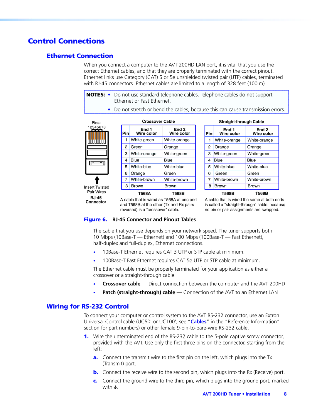
Pins:
12345678
Insert Twisted
Pair Wires
Connector
Crossover Cable
Pin | End 1 | End 2 |
Wire color | Wire color | |
|
|
|
1 | ||
|
|
|
2 | Green | Orange |
3 | ||
|
|
|
4 | Blue | Blue |
|
|
|
5 | ||
|
|
|
6 | Orange | Green |
7 | ||
|
|
|
8 | Brown | Brown |
|
|
|
| T568A | T568B |
A cable that is wired as T568A at one end and T568B at the other (Tx and Rx pairs reversed) is a "crossover" cable.
Pin | End 1 | End 2 |
Wire color | Wire color | |
|
|
|
1 | ||
|
|
|
2 | Orange | Orange |
|
|
|
3 | ||
|
|
|
4 | Blue | Blue |
|
|
|
5 | ||
|
|
|
6 | Green | Green |
7 | ||
|
|
|
8 | Brown | Brown |
|
|
|
| T568B | T568B |
A cable that is wired the same at both ends is called a
Figure 6. RJ-45 Connector and Pinout Tables
The cable that you use depends on your network speed. The tuner supports both 10 Mbps
•
•
The Ethernet cable must be properly terminated for your application as either a crossover or a
•Crossover cable — Direct connection between the computer and the AVT 200HD
•Patch
Wiring for RS-232 Control
To connect your computer or control system to the AVT
1.Wire the unterminated end of the
a.Connect the transmit wire to the first pin on the left, which plugs into the Tx (Transmit) port.
b.Connect the receive wire to the second pin, which plugs into the Rx (Receive) port.
c.Connect the ground wire to the third pin, which plugs into the ground port, marked with _.
AVT 200HD Tuner • Installation | 8 |