Wiring the Power Connector
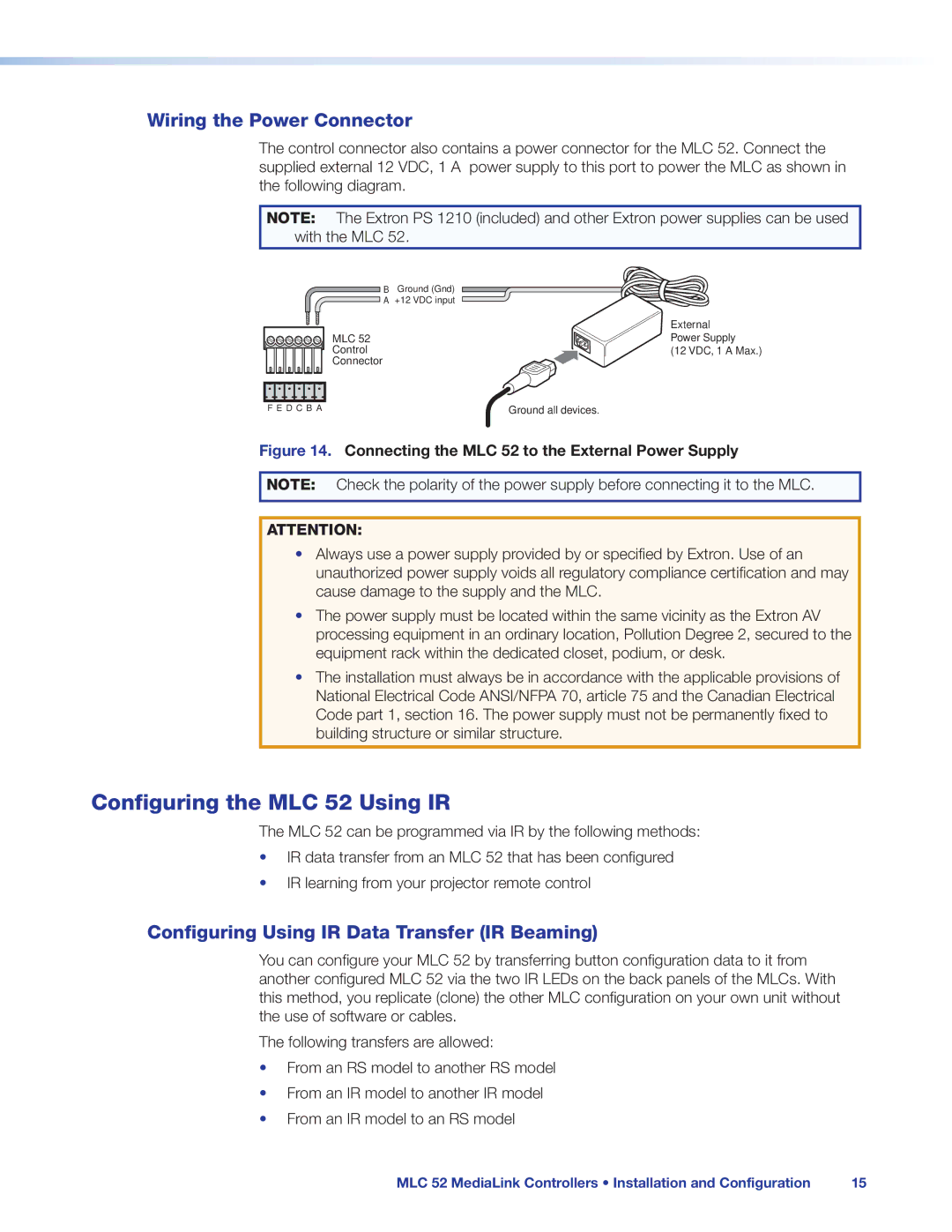
The control connector also contains a power connector for the MLC 52. Connect the supplied external 12 VDC, 1 A power supply to this port to power the MLC as shown in the following diagram.
NOTE: The Extron PS 1210 (included) and other Extron power supplies can be used with the MLC 52.
BGround (Gnd) ![]() A +12 VDC input
A +12 VDC input
MLC 52
Control
Connector
F E D C B A | Ground all devices. |
External
Power Supply
(12 VDC, 1 A Max.)
Figure 14. Connecting the MLC 52 to the External Power Supply
NOTE: Check the polarity of the power supply before connecting it to the MLC.
ATTENTION:
•Always use a power supply provided by or specified by Extron. Use of an
unauthorized power supply voids all regulatory compliance certification and may cause damage to the supply and the MLC.
•The power supply must be located within the same vicinity as the Extron AV processing equipment in an ordinary location, Pollution Degree 2, secured to the equipment rack within the dedicated closet, podium, or desk.
•The installation must always be in accordance with the applicable provisions of National Electrical Code ANSI/NFPA 70, article 75 and the Canadian Electrical Code part 1, section 16. The power supply must not be permanently fixed to building structure or similar structure.
Configuring the MLC 52 Using IR
The MLC 52 can be programmed via IR by the following methods:
•IR data transfer from an MLC 52 that has been configured
•IR learning from your projector remote control
Configuring Using IR Data Transfer (IR Beaming)
You can configure your MLC 52 by transferring button configuration data to it from another configured MLC 52 via the two IR LEDs on the back panels of the MLCs. With this method, you replicate (clone) the other MLC configuration on your own unit without the use of software or cables.
The following transfers are allowed:
•From an RS model to another RS model
•From an IR model to another IR model
•From an IR model to an RS model
MLC 52 MediaLink Controllers • Installation and Configuration | 15 |
