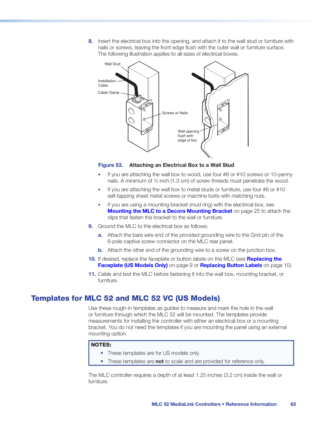
8.Insert the electrical box into the opening, and attach it to the wall stud or furniture with nails or screws, leaving the front edge flush with the outer wall or furniture surface. The following illustration applies to all sizes of electrical boxes.
Wall Stud
Installation
Cable
Cable Clamp
Screws or Nails
Wall opening ![]() flush with
flush with
edge of box
Figure 53. Attaching an Electrical Box to a Wall Stud
•If you are attaching the wall box to wood, use four #8 or #10 screws or
•If you are attaching the wall box to metal studs or furniture, use four #8 or #10
•If you are using a mounting bracket (mud ring) with the electrical box, see Mounting the MLC to a Decora Mounting Bracket on page 25 to attach the clips that fasten the bracket to the wall or furniture.
9.Ground the MLC to the electrical box as follows:
a.Attach the bare wire end of the provided grounding wire to the Gnd pin of the
b.Attach the other end of the grounding wire to a screw on the junction box.
10.If desired, replace the faceplate or button labels on the MLC (see Replacing the Faceplate (US Models Only) on page 9 or Replacing Button Labels on page 10).
11.Cable and test the MLC before fastening it into the wall box, mounting bracket, or furniture.
Templates for MLC 52 and MLC 52 VC (US Models)
Use these
NOTES:
•These templates are for US models only.
•These templates are not to scale and are provided for reference only.
The MLC controller requires a depth of at least 1.25 inches (3.2 cm) inside the wall or furniture.
MLC 52 MediaLink Controllers • Reference Information | 63 |