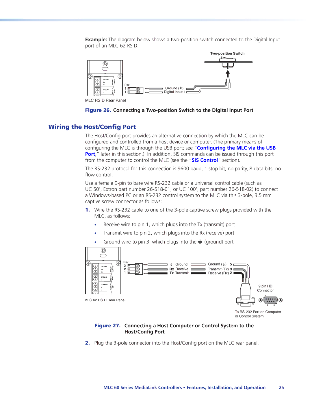
Example: The diagram below shows a
GROUND
Rx
Tx
GROUND 1
HOST/ | CONFIG |
DIGITAL | INPUT |
Pin: | Ground ( ) |
2 | |
1 | Digital Input 1 |
1 | RELAYS |
COMMON |
|
MLC RS D Rear Panel | |
2 | N/O |
| |
Figure 26. Connecting a Two-position Switch to the Digital Input Port
Wiring the Host/Config Port
The Host/Config port provides an alternative connection by which the MLC can be configured and controlled from a host device or computer. (The primary means of configuring the MLC is through the USB port; see “Configuring the MLC via the USB Port,” later in this section.) In addition, SIS commands can be issued through this port from the computer to control the MLC (see the “SIS Control” section).
The
Use a female
UC 50', Extron part number
1.Wire the
MLC, as follows:
•Receive wire to pin 1, which plugs into the Tx (transmit) port
•Transmit wire to pin 2, which plugs into the Rx (receive) port
•Ground wire to pin 3, which plugs into the _ (ground) port
| HOST/ CONFIG | Pin: |
Tx | 3 | |
GROUND |
| |
Rx |
| 2 |
| DIGITAL INPUT | 1 |
1 |
| |
GROUND |
|
|
1 | RELAYS N/O |
|
COMMON |
|
|
2 |
|
|
GROUND | S |
|
Tx/IR | IR/ |
|
MLC 62 RS D Rear Panel | ||
GROUND |
| |
Tx | PWR 12V MAXA0.2 |
|
GROUND |
| |
+12 VDC |
|
|
Ground
Rx Receive
Tx Transmit
Ground ( ![]() ) 5
) 5
Transmit (Tx) 3
Receive (Rx) 2 ![]()
9 pin HD
Connector
5 1
9 6
To
Figure 27. Connecting a Host Computer or Control System to the Host/Config Port
2.Plug the
MLC 60 Series MediaLink Controllers • Features, Installation, and Operation | 25 |