Using the Command and Response Table
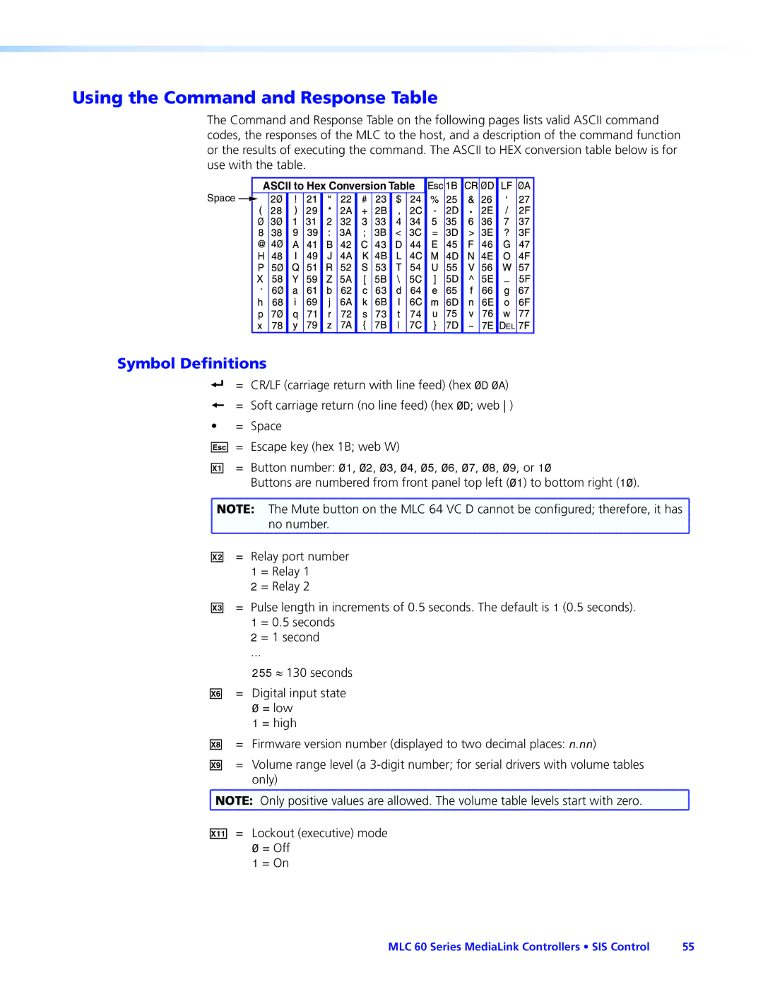
The Command and Response Table on the following pages lists valid ASCII command codes, the responses of the MLC to the host, and a description of the command function or the results of executing the command. The ASCII to HEX conversion table below is for use with the table.
ASCII to Hex Conversion Table
Space ![]()
•
Symbol Definitions
] = CR/LF (carriage return with line feed) (hex 0D 0A)
}= Soft carriage return (no line feed) (hex 0D; web )
• = Space
E = Escape key (hex 1B; web W)
X! = Button number: 01, 02, 03, 04, 05, 06, 07, 08, 09, or 10
Buttons are numbered from front panel top left (01) to bottom right (10).
![]() NOTE: The Mute button on the MLC 64 VC D cannot be configured; therefore, it has
NOTE: The Mute button on the MLC 64 VC D cannot be configured; therefore, it has ![]()
no number.
X@ = Relay port number
1 = Relay 1
2 = Relay 2
X#
X^
=Pulse length in increments of 0.5 seconds. The default is 1 (0.5 seconds). 1 = 0.5 seconds
2 = 1 second
...
255 ≈ 130 seconds
=Digital input state 0 = low
1 = high
X* = Firmware version number (displayed to two decimal places: n.nn)
X( = Volume range level (a
![]() NOTE: Only positive values are allowed. The volume table levels start with zero.
NOTE: Only positive values are allowed. The volume table levels start with zero.
X1! = Lockout (executive) mode 0 = Off
1 = On
MLC 60 Series MediaLink Controllers • SIS Control | 55 |