|
|
|
|
|
|
|
|
|
|
|
|
|
|
|
|
| Tx | HOST/ | CONFIG |
| |
|
|
|
|
|
|
| ||||
|
|
|
|
|
| GROUND |
|
|
|
|
|
|
|
|
|
| Rx | DIGITAL | INPUT |
| |
|
|
|
|
|
| 1 |
| |||
|
|
|
|
|
| GROUND | RELAYS | N/O |
| |
|
|
|
|
|
| 1 |
| |||
|
|
|
|
|
|
| ||||
|
|
|
|
|
| COMMON |
|
|
|
|
|
|
|
|
|
| 2 | B |
|
|
|
|
|
|
|
|
|
|
|
|
| |
|
|
|
|
|
|
|
|
|
| |
|
|
|
|
|
|
|
|
|
| |
|
|
|
|
|
|
|
|
|
| |
|
|
|
|
|
|
|
|
|
| |
|
|
|
|
|
| GROUND | PORT IR/S |
| ||
|
|
|
|
|
| Tx/IR |
| |||
|
|
|
|
|
|
|
|
|
| |
| MLC | RS | GROUND |
| ||||||
| D Rear Panel |
| ||||||||
|
|
|
|
|
| Tx |
|
|
|
|
|
|
|
|
|
|
|
| X |
| |
|
| Power |
|
|
| Supply |
|
Pin: |
|
| Ground ( ) |
3 | Ground ( ) |
| |
2 | Signal |
| 110/220 V |
1 |
|
|
|
|
| Low Voltage | Motorized |
|
| Screen Control | |
|
| Screen | |
|
|
|
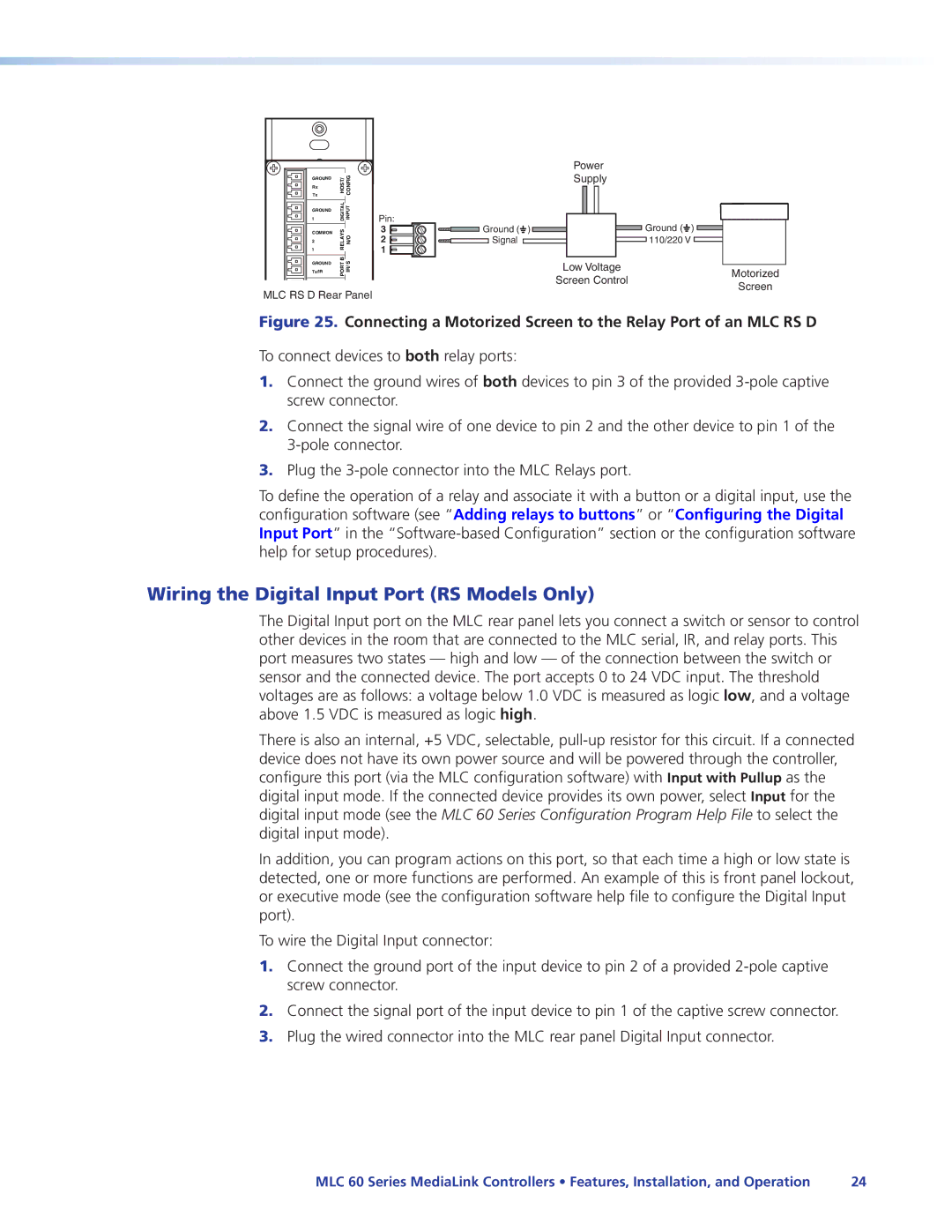
Figure 25. Connecting a Motorized Screen to the Relay Port of an MLC RS D
To connect devices to both relay ports:
1.Connect the ground wires of both devices to pin 3 of the provided
2.Connect the signal wire of one device to pin 2 and the other device to pin 1 of the
3.Plug the
To define the operation of a relay and associate it with a button or a digital input, use the configuration software (see “Adding relays to buttons” or “Configuring the Digital Input Port” in the
Wiring the Digital Input Port (RS Models Only)
The Digital Input port on the MLC rear panel lets you connect a switch or sensor to control other devices in the room that are connected to the MLC serial, IR, and relay ports. This port measures two states — high and low — of the connection between the switch or sensor and the connected device. The port accepts 0 to 24 VDC input. The threshold voltages are as follows: a voltage below 1.0 VDC is measured as logic low, and a voltage above 1.5 VDC is measured as logic high.
There is also an internal, +5 VDC, selectable,
In addition, you can program actions on this port, so that each time a high or low state is detected, one or more functions are performed. An example of this is front panel lockout, or executive mode (see the configuration software help file to configure the Digital Input port).
To wire the Digital Input connector:
1.Connect the ground port of the input device to pin 2 of a provided
2.Connect the signal port of the input device to pin 1 of the captive screw connector.
3.Plug the wired connector into the MLC rear panel Digital Input connector.
MLC 60 Series MediaLink Controllers • Features, Installation, and Operation | 24 |