8190001
24-HourService Hotline
JUNE
NOTICE
NOTICE TO U.S. CUSTOMERS
NOTICE TO OWNERS OF UNITS EQUIPPED WITH COMPUTERS
CANADA
DANGER
DANGER
DANGER
DANGER
CHAPTER 1: Service Procedures
H50 SERIES GAS FRYERS TABLE OF CONTENTS
CHAPTER 2: Parts List
Basket Lift Assemblies and Component Parts
H50 SERIES GAS FRYERS TABLE OF CONTENTS
2.13.11
H50 SERIES GAS FRYERS TABLE OF CONTENTS
H50 SERIES GAS FRYERS
CHAPTER 1: SERVICE PROCEDURES
1.1Functional Description
the other leg of the heat relay coils, which then close electronic switches in the 24 VAC circuit to provide current to the ignition module. Circuitry in the ignition module sends 24 VAC to the gas valve via a normally closed high-limitswitch and, in fryers with built-infiltration systems, a normally closed drain safety switch. Simultaneously, the module causes the ignitor to spark for 4 seconds to light the burner. A flame sensor verifies the burner ignition by measuring the flow of microamps through the flame. If the burner does not light or is extinguished, current to the ignition module is cut, the gas valve closes, and the ignition module “locks out” until the power switch is turned off and then back on. A probe monitors the temperature in the frypot. When the programmed setpoint temperature is reached, resistance in the probe causes the heat cycle circuitry in the controller to cut off current flow through the heat relay. This in turn cuts off the 24 VAC to the ignition module, causing the gas valve to close
These standard interface boards are also used in a number of fryer types besides the H50 Series. The
LEFT VAT
INTERFACE BOARD
FULL OR RIGHT VAT
CURRENT FLOW THROUGH INTERFACE BOARDS 806-3398AND
1.3Cleaning the Gas Valve Vent Tube
1.2Accessing Fryers for Servicing DANGER
1.4Checking the Burner Manifold Gas Pressure
5.To adjust the burner gas pressure, remove the cap from the gas valve regulator and adjust to the correct pressure
1.6Replacing Fryer Components
1.5Measuring Flame Current
1.6.4 Replacing an Ignition Module
1.6.3 Replacing the Interface Board
1.6.5 Replacing an Ignitor Assembly DANGER
5.Reinstall the blower shield or shield assembly
Non-CEUnits and CE Units Built After April
Adjusting Air/Gas Mixture
Adjusting Air/Gas Mixture
1.6.7 Replacing a Gas Valve DANGER
CE Units Built Through April
1.6.8 Replacing a Burner Assembly DANGER
1.6.9 Replacing the Frypot
18.Reverse steps 1-16to reassemble fryer
10.Remove the flue assembly
Full Vat Illustrated
Disassembling A Frypot
Spacer
Spacers
Full Vat Illustrated
Re-assemblingA Frypot
Apply cement
here
1-20
31.Remove and replace the plenum gaskets
1.7.1 Ignition Failures
1.7Troubleshooting and Problem Isolation
1.7.2 Improper Burner Functioning
VOLTS
DANGER
Non-CEStandard for Incoming Gas Pressures
1.7.3 Improper Temperature Control
1.7.4 Computer-RelatedProblems
1.7.5Filtration Problems
1-27
1-28
1.7.7 Basket Lift Malfunctions
1.7.6 Leakage
P/N 806-8530SPTYPICAL
100/120V Modular Basket Lift Assembly
•Binding/jamming problems
1.7.8 Interpretation of Digital Controller Lights
1.8Troubleshooting Guide
PROBABLE CAUSES
PROBLEM
CORRECTIVE ACTION
Check
With Interface Board 806-3398or 106-0386and
24 VOLT CIRCUIT
LEFT VAT
FULL OR RIGHT VAT
24 VOLT CIRCUIT
One 807-3366FV Ignition Module
With Interface Board 806-3398or 106-0386and
J3 PIN
PROBABLE CAUSES
PROBLEM
CORRECTIVE ACTION
Check
OHMS
Probe Resistance Chart
OHMS
OHMS
H50 SERIES — FULL-VAT— JUNE 1996 - JULY
1.9 Simplified Wiring Diagrams
LINE VOLTAGE
LEFT IGNITION
LEFT IGNITION
LINE VOLTAGE
RIGHT IGNITION
MODULE
AIR SWITCH ONLY ON CE AND SOME EXPORT UNITS
ONE DUAL FUNCTION HEAT/BLOWER RELAY K3
LINE VOLTAGE
DUAL-SPARK IGNITION MODULE
THREE RELAYS: K1 & K2 HEAT AND K4 BLOWER
H50 SERIES — DUAL-VAT— JUNE 1996 - JULY
DRAIN SAFETY SWITCH
AIR SWITCH
1-42
TWO DUAL-FUNCTIONHEAT/BLOWER RELAYS K1 & K2
LEFT IGNITION
RIGHT IGNITION
LEFT VAT
1.10Principal Wiring Connections
RIGHT OR FULL VAT
T LI
FPH150 ONLY NON-CE
1.11WIRING DIAGRAMS - MAIN
8051150A
FPH150 ONLY CE
ON SOME OLDER UNITS C4 HAD A 6-PIN PLUG
FULL VAT
FULL VAT
8050526D
8050344A
H50 SERIES MANUFACTURED GAS UNITS
120V CONFIGURATION SHOWN 8050500E
8050530D
CE Transformer Boxes
LEFT SIDE
1.13WIRING DIAGRAMS – BASKET LIFTS
RIGHT SIDE
BLUE
RIGHT SIDE
ORANGE
WHITE
A 6-PINPLUG
EARLIER UNITS
ON SOME
C4 WAS
8050902C
1.14WIRING DIAGRAMS – FILTER BOXES
Oil Return/Disposal Wand Wiring Japan/Lotteria
1.15WIRING DIAGRAMS – OIL RETURN
Oil Return/Disposal Wand Wiring Sonic
Oil Return/Wand Wiring Japan
Accessories
H50 SERIES GAS FRYERS CHAPTER 2: PARTS LIST
18803-0197Fryer’s Friend 27” Clean-outRod
17803-0209Brush, Frypot Cleaning
15810-0074 Quick-DisconnectFitting, 1-InchMale
16810-0073 Quick-DisconnectFitting, 1-InchFemale
2.2.1Bell Crank Basket Lifts
2.2Basket Lift Assemblies and Component Parts
ITEM PART #
208-250VConfiguration
100-120VConfiguration
2.2.2 Modular Basket Lifts
Wire Assemblies
Connector, Panel Mount
PART #
COMPONENT
ITEM
2.3Blower Assemblies and Associated Components
COMPONENT
PART #
ITEM
COMPONENT
PART #
ITEM
2.5Cabinet Assemblies and Component Parts
2.5.1FPH150 Cabinet Assembly
ITEM
PART #
2.5.2 FPH50 Batteries
See Page 2-10for access opening covers
Back, Lower Cabinet
COMPONENT
910-7657
910-9416
ITEM
2.5.3 FH150, MJH150, and Spreader Cabinets
COMPONENT
MJH50 Batteries
2.5.4
ITEM
PART #
2.5.5FMH50 Batteries with Built-InFiltration
See Page 2-14for Leg Pad Assembly
FMH150 FILTER ON LEFT
FMH250 FILTER BETWEEN FRYERS
1910-7480Trim, Filter Cabinet Top
ITEM PART #
2.5.6Filter Magic Add-OnCabinetry
See Page 2-10for access opening covers
NOTE: Items 1-3and 9 from Page 2-16,and Item
NOTE: Item 9 from Page 2-16,and Item 20 or
COMPONENT
Side, Left Cabinet, w/Access Openings
2.6Casters, Legs, and Restraints
ITEM PART #
Not illustrated 2-20
Page
NOTES
ITEM PART #
ITEM
2.9Controller Assemblies
PART #
COMPONENT
2.9Controller Assemblies cont
Door Assembly, Complete for use on FPH50 units
ITEM
PART#
ITEM
2.11Drain System Components
COMPONENT
PART #
ITEM
COMPONENT
806-6374
1806-6374 2816-0420 3KIT-0257SP 4826-1382
ITEM
COMPONENT
PART #
ITEM
COMPONENT
806-6374SP
806-6374
COMPONENT
ITEM
2.12.1 Drain Valves and Drain Extensions
PART #
COMPONENT
806-7915SP Complete Assembly, Left
806-4145SP
806-7916SP Complete Assembly, Right
COMPONENT Complete Assembly, Domestic Units
ITEM
2.12.3 FMH50 Dual Vat 1-InchValve Assemblies
PART #
COMPONENT
ITEM
2.12.4 FMH50 Full Vat 1¼-inchValve Assembly
806-8791SP
COMPONENT
Complete Assembly, Right for CE, use 806-6608SP
Complete Assembly, Left for CE, use 806-6609SP
ITEM
PART #
ITEM
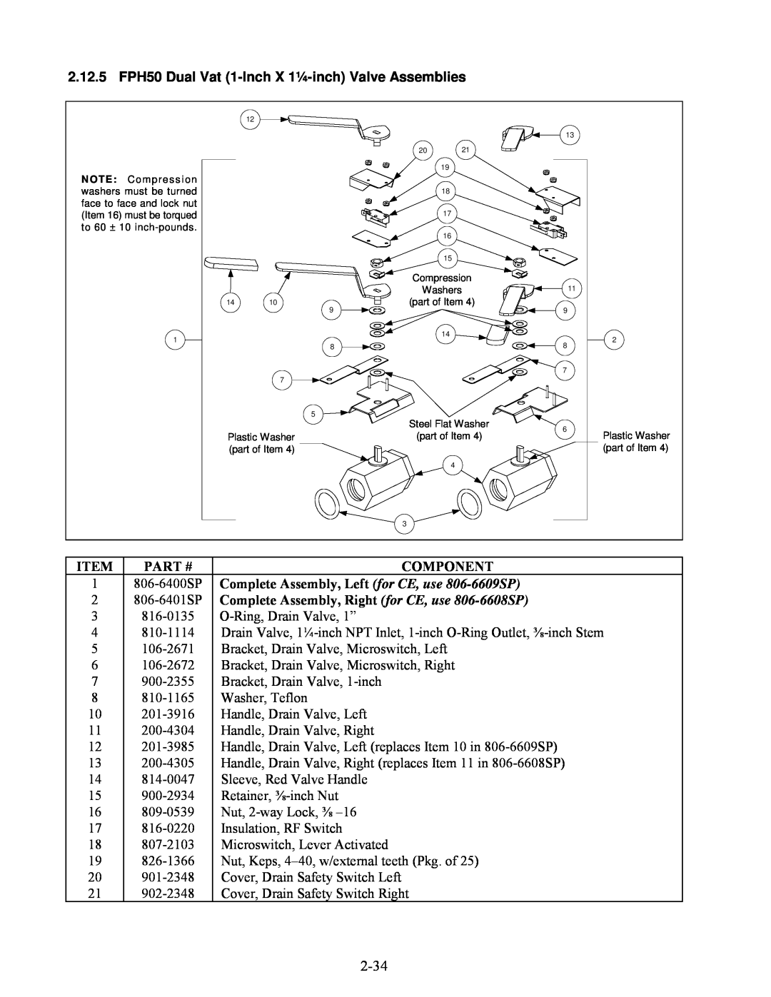
2.12.6 FPH50 Full Vat 1¼-inchValve Assemblies
Components Used on Both Designs
ITEM PART #
ITEM
2.13.2 FootPrint III Filter Pan Assembly
PART #
COMPONENT
806-5954SP Base Assembly w/Casters Items
806-9619SP Base Assembly w/o Casters Items 1-
2.13.3 FootPrint III Filter Base Assemblies
ITEM
Vat Configuration
Typical Full Vat Configurations
Motors
21Detail of Motor, Pump, and
COMPONENT
PART #
Pump Motor
Standard FP III Configuration Prior to August
FPH150 Configuration
Motor and Gasket Kits
COMPONENT
FPH350 with Dual
CONFIGURATIONS
Vat on Left
TYPICAL FOOTPRINT
PART #
ITEM
COMPONENT
807-2484
See Page 2-48for Oil Return Handle Components
FPH350-2LRear Flush Typical
1813-0165Elbow, ½-inchx 90º Street
ITEM PART #
TYPICAL CONFIGURATION
Right Oil Return Valve Assembly
Right Handle and Switch Assembly
1807-2484Valve, Solenoid Vent
ITEM PART #
Control Panel Assembly
Assembly
2.13.9 FPH150-2Oil Return Plumbing
806-6358SP
PART #
ITEM
COMPONENT
806-6309SP
806-3470SP
ITEM
COMPONENT
Power Shower Assembly, Full Vat, Complete
2.13.11 Power Shower Assemblies All Models
Power Shower Assembly, Dual Vat, Complete
ITEM
Disposal
2.13
Systems
Plumbing
COMPONENT
PART #
806-9087SP
PART #
2.13.13 Assembly Wand Plumbing Japan
COMPONENT
2.14Frypot Assemblies and Component Parts
2.13.14Oil Disposal Wand Assembly
Replacement Frypot Assemblies, Complete
Replacement Insulation Kits
2.14.2 Full Vat Frypot Assembly, Component Parts
Full Vat Frypot Assembly Typical
and gaskets required when replacing
See Page 2-58for
PART #
ITEM
28823-0969Plenum, Full Vat for CE units, use
Assembly, Component Parts
Dual Vat Frypot Assembly Typical
2.14.3 Dual Vat Frypot
See Page 2-58for P/N’s
PART #
ITEM
COMPONENT
CE FM/MJH350-4RTypical
2.15.1 FM/MJH50 Gas Manifold Assemblies
NON-CE FM/MJH350-4RTypical
See Page 2-63for details of gas valve assemblies
1810-0959FM/MJH150 Gas Manifold
ITEM PART #
2.15.2 Gas Valves, Gas Lines and Fittings
1Gas Valve and Bushing, Non-CE
ITEM PART #
2.16Probe, Probe Guard and Thermostat
Temperature Probe Assembly
COMPONENT
826-1177
ITEM
2.18.1 Filter Box Components
PART #
COMPONENT
Transformer Box Components
2.18.2
FPH150
FPH150
PART #
ITEM
COMPONENT
1807-0012Relay, 18 Amp ⅓-HP24V Coil
Not illustrated
Filter Box Wiring
2-69
PART #
Power Cords
Main Wiring Harnesses
ITEM
PART #
Transformer Box Plug Assemblies
Gas Valve Wiring
ITEM
2.20Wiring Connectors and Pin Terminals
COMPONENT
THIS PAGE INTENTIONALLY LEFT BLANK
SERVICE HOTLINE