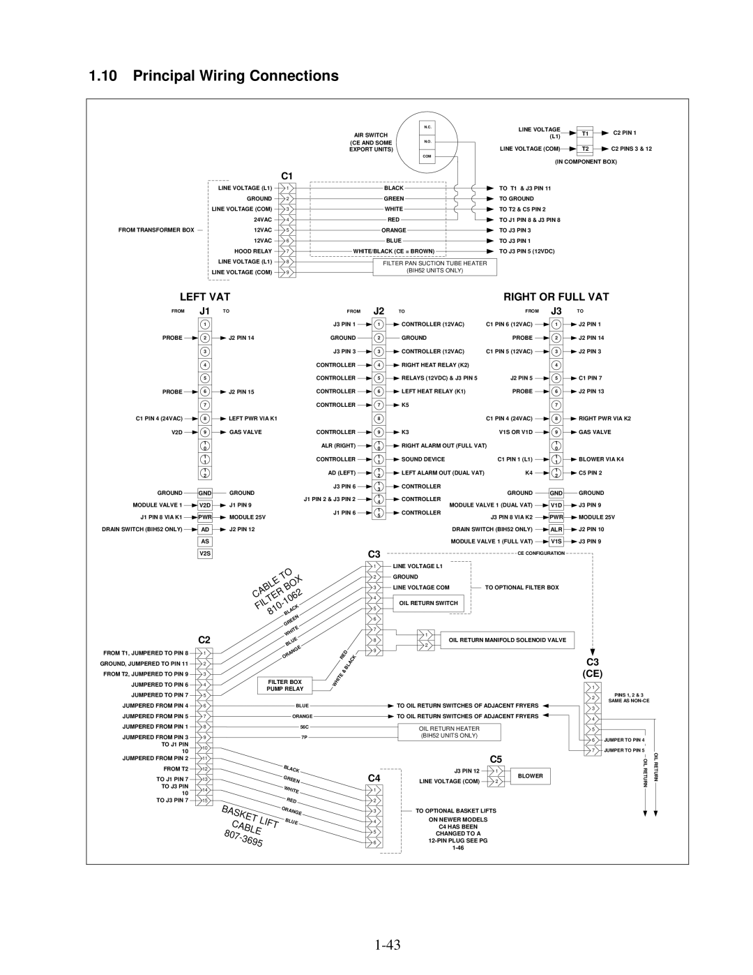
1.10Principal Wiring Connections

AIR SWITCH

(CE AND SOME EXPORT UNITS)

N.C.

N.O.

COM

LINE VOLTAGE


C2 PIN 1

T1


(L1)


LINE VOLTAGE (COM)


C2 PINS 3 & 12

T2


(IN COMPONENT BOX)

C1


LINE VOLTAGE (L1)


1


BLACK


TO T1 & J3 PIN 11


GROUND


2


GREEN


TO GROUND


LINE VOLTAGE (COM)


3


WHITE


TO T2 & C5 PIN 2


24VAC


4


RED


TO J1 PIN 8

& J3 PIN 8


FROM TRANSFORMER BOX


12VAC


5


ORANGE


TO J3 PIN 3


12VAC


6


BLUE


TO J3 PIN 1


HOOD RELAY


7


WHITE/BLACK (CE = BROWN)


TO J3 PIN 5

(12VDC)


LINE VOLTAGE (L1)


8


FILTER PAN SUCTION TUBE HEATER


LINE VOLTAGE (COM)


9


(BIH52 UNITS ONLY)


LEFT VAT

RIGHT OR FULL VAT

FROM J1 TO

1

PROBE 2 J2 PIN 14

3

4

5

PROBE 6 J2 PIN 15

7

C1 PIN 4 (24VAC) 8 LEFT PWR VIA K1

V2D 9 GAS VALVE

1

0

1

1

1

2

GROUND GND GROUND

MODULE VALVE 1 V2D J1 PIN 9

J1 PIN 8 VIA K1 PWR MODULE 25V

DRAIN SWITCH (BIH52 ONLY) AD J2 PIN 12

AS

FROM J2

J3 PIN 1 1

GROUND 2

J3 PIN 3 3

CONTROLLER 4

CONTROLLER 5

CONTROLLER 6

CONTROLLER 7


8

CONTROLLER


9


ALR (RIGHT)


1

0


CONTROLLER


1

1


AD (LEFT)


1

2


J3 PIN 6


1

3


J1 PIN 2 & J3 PIN 2


1

4


J1 PIN 6


1

5


TO

FROM


J3


TO


CONTROLLER (12VAC)

C1 PIN 6 (12VAC)


1


J2 PIN 1


GROUND

PROBE


2


J2 PIN 14


CONTROLLER (12VAC)

C1 PIN 5 (12VAC)


3


J2 PIN 3


RIGHT HEAT RELAY (K2)

J2 PIN 5


4


C1 PIN 7


RELAYS (12VDC) & J3 PIN 5


5


LEFT HEAT RELAY (K1)

PROBE


6


J2 PIN 13


K5

C1 PIN 4 (24VAC)


7


RIGHT PWR VIA K2


8


K3

V1S OR V1D


9


GAS VALVE


RIGHT ALARM OUT (FULL VAT)

1


0


SOUND DEVICE

C1 PIN 1 (L1)


1


BLOWER VIA K4


1


LEFT ALARM OUT (DUAL VAT)

K4


1


C5 PIN 2


2


CONTROLLER


CONTROLLER

GROUND


GND


GROUND


MODULE VALVE 1 (DUAL VAT)


V1D


J3 PIN 9


CONTROLLER


J3 PIN 8 VIA K2


PWR


MODULE 25V


DRAIN SWITCH (BIH52 ONLY)


ALR


J2 PIN 10


J3 PIN 9


MODULE VALVE 1 (FULL VAT)


V1S


V2S

C3

CE CONFIGURATION


C2

FROM T1, JUMPERED TO PIN 8


1


GROUND, JUMPERED TO PIN 11


2


FROM T2, JUMPERED TO PIN 9


3


JUMPERED TO PIN 6


4


JUMPERED TO PIN 7


5


JUMPERED FROM PIN 4


6


JUMPERED FROM PIN 5


7


JUMPERED FROM PIN 1


8


JUMPERED FROM PIN 3


9


TO J1 PIN


10

10


JUMPERED FROM PIN 2


11


FROM T2


12


TO J1 PIN 7


13


TO J3 PIN


14

10


TO J3 PIN 7


15


O


T


X


E


O


BL


B

2


A


R


C


E


6


T


0


L


1


I


-


C


F


0


1


K


A


8


B


L


N


E


E


R


G


E


IT


H


W


E


U


L


B


E


G


N


A


R


O


FILTER BOX


PUMP RELAY


BLUE


ORANGE


56C


7P


B

LA


G


CK


RE


W


EN


HI

TE


B


R

ED

A


S


OR

AN


GE


K


E


BLUE


C


T LI


FT


A


B


807-


L


3

6

E


95


R


H

IT

E

W


ED

&B


A

C

K

L


1 LINE VOLTAGE L1

2GROUND

3


LINE VOLTAGE COM


TO OPTIONAL FILTER BOX


4

OIL RETURN SWITCH

5

6

7

1

8OIL RETURN MANIFOLD SOLENOID VALVE

2

9

TO OIL RETURN SWITCHES OF ADJACENT FRYERS

TO OIL RETURN SWITCHES OF ADJACENT FRYERS

OIL RETURN HEATER (BIH52 UNITS ONLY)


C5

C4

J3 PIN 12

1

LINE VOLTAGE (COM)

BLOWER

2

1


2

3 TO OPTIONAL BASKET LIFTS

4ON NEWER MODELS

C4 HAS BEEN

5CHANGED TO A

612-PIN PLUG SEE PG

1-46

C3

(CE)

1

2PINS 1, 2 & 3

SAME AS NON-CE

3

4


5


6


JUMPER TO PIN 4


7


JUMPER TO PIN 5


OIL RETURN


OIL RETURN


1-43

Page 49
Image 49
Frymaster H50 Series manual Principal Wiring Connections, Left VAT Right or Full VAT

H50 Series specifications

The Frymaster H50 Series represents a significant advancement in commercial deep frying technology, designed specifically for high-volume food service operations. With a focus on efficiency, ease of use, and exceptional frying quality, this series is a favorite among restaurateurs seeking to optimize their kitchen performance.

One of the standout features of the Frymaster H50 Series is its Energy Efficiency. These fryers are engineered to provide superior heat transfer, allowing for quicker recovery times and reduced energy consumption. This is crucial in a busy kitchen where every second counts, and maintaining consistent oil temperatures is vital for producing perfectly cooked food.

The H50 Series incorporates the advanced computer control platform, which offers precise temperature control and monitoring. This technology allows operators to set specific frying times and temperatures for various foods, ensuring consistency and quality in every batch. Additionally, these controls include built-in safety features that help prevent overheating and potential hazards, promoting a safer working environment.

Flexibility is another hallmark of the H50 Series. These fryers can accommodate a wide range of menu items, from fries to chicken and seafood, making them an ideal choice for diverse culinary applications. The fryers also come with adjustable basket configurations and options for single or multiple frying pots, providing versatility for varying production demands.

The design of the Frymaster H50 Series is focused on ease of use and maintenance. The fryers feature a user-friendly interface, making it simple for staff to operate them even during peak hours. Maintenance is streamlined through easy access to components, ensuring that cleaning and servicing can be carried out quickly, minimizing downtime and enhancing productivity.

Durability is another key characteristic of the Frymaster H50 Series. Constructed with high-quality materials, these fryers are built to withstand the rigors of a commercial kitchen. The stainless steel exterior not only adds to the aesthetic appeal but also offers resistance to corrosion and damage, ensuring that these fryers will perform reliably over time.

In summary, the Frymaster H50 Series combines energy efficiency, advanced technology, operational flexibility, ease of use, and durability. This makes it a top choice for food service establishments aiming to deliver high-quality, consistently fried foods while optimizing kitchen operations. Whether you're upgrading your current equipment or starting a new venture, the H50 Series is a powerful ally in the world of commercial frying.