7.3General operation of indication/operation panel
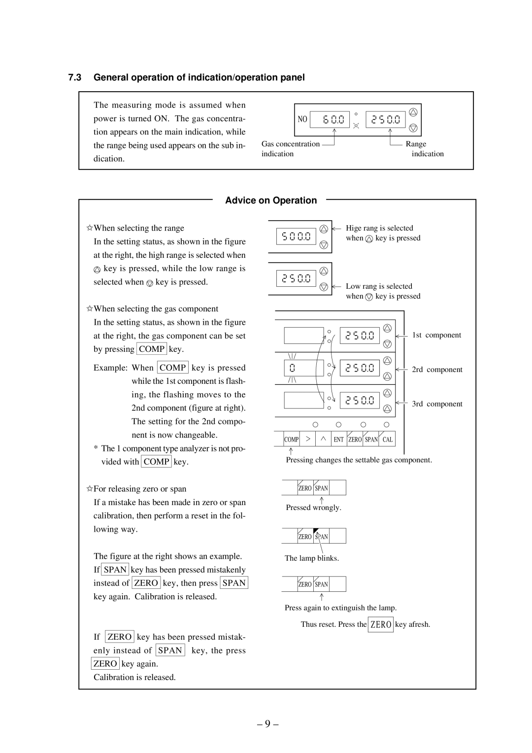
The measuring mode is assumed when power is turned ON. The gas concentra- tion appears on the main indication, while the range being used appears on the sub in- dication.
NO
Gas concentration | Range |
indication | indication |
Advice on Operation
✩When selecting the range
In the setting status, as shown in the figure at the right, the high range is selected when ![]() key is pressed, while the low range is selected when
key is pressed, while the low range is selected when ![]() key is pressed.
key is pressed.
Hige rang is selected when ![]() key is pressed
key is pressed
Low rang is selected when ![]() key is pressed
key is pressed
✩When selecting the gas component |
In the setting status, as shown in the figure |
at the right, the gas component can be set |
by pressing COMP key. |
Example: When COMP key is pressed |
while the 1st component is flash- |
ing, the flashing moves to the |
2nd component (figure at right). |
The setting for the 2nd compo- |
nent is now changeable. |
* The 1 component type analyzer is not pro- |
COMP | ENT ZERO SPAN CAL |
1st component
2rd component
3rd component
vided with COMP key. |
✩For releasing zero or span |
If a mistake has been made in zero or span |
calibration, then perform a reset in the fol- |
lowing way. |
The figure at the right shows an example. |
If SPAN key has been pressed mistakenly |
instead of ZERO key, then press SPAN |
key again. Calibration is released. |
If ZERO key has been pressed mistak- |
enly instead of SPAN key, the press |
ZERO key again. |
Calibration is released. |
Pressing changes the settable gas component.
ZERO SPAN
Pressed wrongly.
ZERO SPAN
The lamp blinks.
ZERO SPAN
Press again to extinguish the lamp.
Thus reset. Press the ZERO key afresh.
– 9 –
