(6)Replacement of NO2/NO converter catalyst
(a)Turn off power supply to the converter.
(b)After half an hour, remove q w e, and extract r upward and downward, respectively. Pay attention not to suffer a burn. In addition, carefully handle the ceramic pipe for preventing breakage. When remov- ing r , e will fall simultaneously. So prepare a catalyst receiver.
(c)Wind glass wool on the tip of r and insert it from the bottom together with q. Inject one pack of new catalyst from the top. Set weon the top side. (This step is unnecessary when a membrane filter is pro- vided at the later stage.)
(d)Connect the pipe, set the temperature controller at 220° C (200° C for NO/CO analyzer), and turn on
power supply.
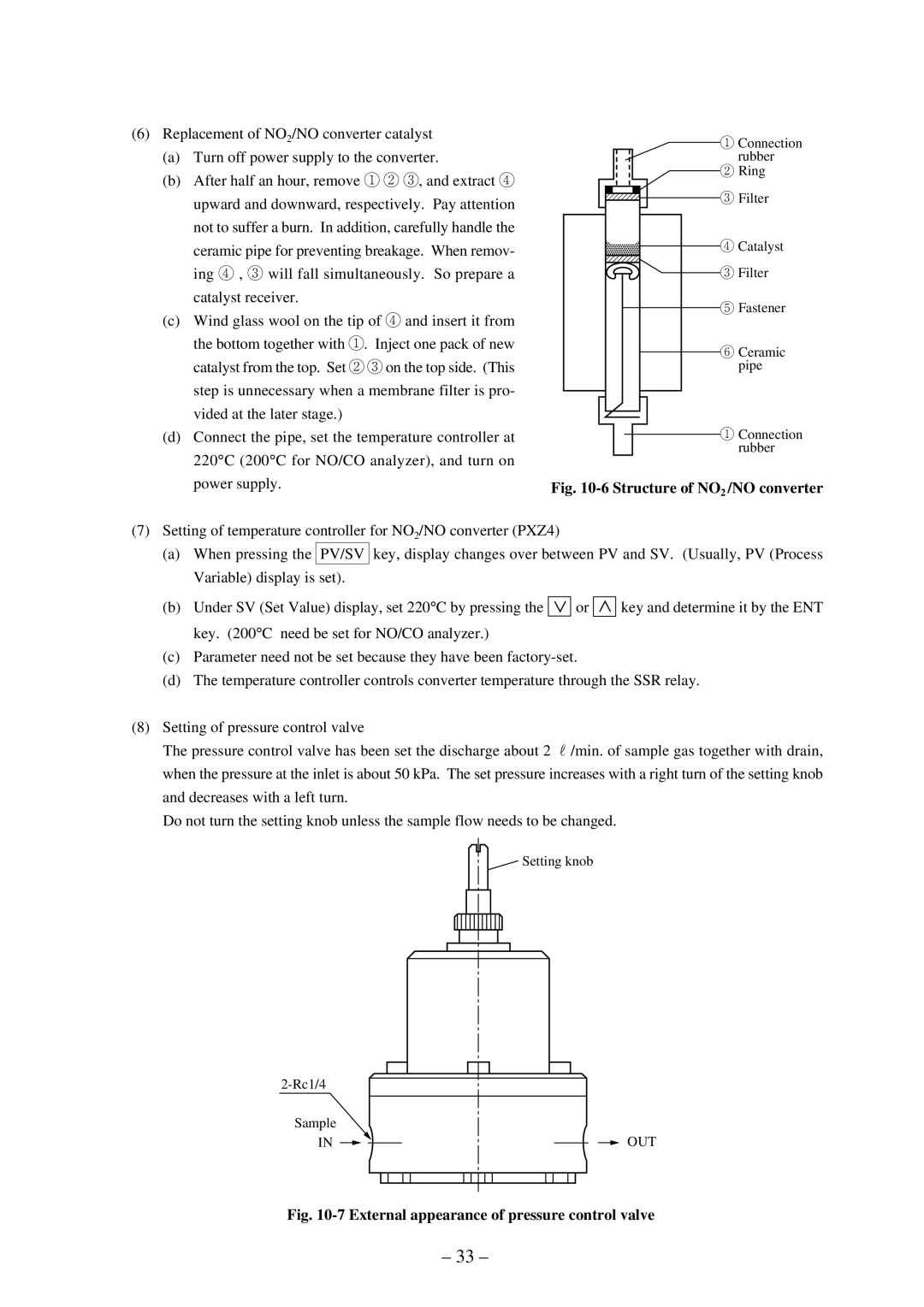
q Connection rubber
![]() w Ring
w Ring
e Filter
r Catalyst
e Filter
t Fastener
y Ceramic pipe
q Connection rubber
Fig. 10-6 Structure of NO2 /NO converter
(7)Setting of temperature controller for NO2/NO converter (PXZ4)
(a)When pressing the PV/SV key, display changes over between PV and SV. (Usually, PV (Process Variable) display is set).
(b)Under SV (Set Value) display, set 220° C by pressing the ![]()
![]()
![]() or
or ![]()
![]()
![]() key and determine it by the ENT key. (200° C need be set for NO/CO analyzer.)
key and determine it by the ENT key. (200° C need be set for NO/CO analyzer.)
(c)Parameter need not be set because they have been
(d)The temperature controller controls converter temperature through the SSR relay.
(8)Setting of pressure control valve
The pressure control valve has been set the discharge about 2 N/min. of sample gas together with drain, when the pressure at the inlet is about 50 kPa. The set pressure increases with a right turn of the setting knob and decreases with a left turn.
Do not turn the setting knob unless the sample flow needs to be changed.
![]() Setting knob
Setting knob
Sample
IN | OUT |
Fig. 10-7 External appearance of pressure control valve
– 33 –