(2)LBA mode
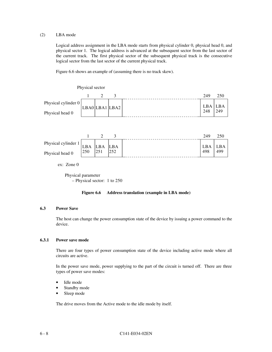
Logical address assignment in the LBA mode starts from physical cylinder 0, physical head 0, and physical sector 1. The logical address is advanced at the subsequent sector from the last sector of the current track. The first physical sector of the subsequent physical track is the consecutive logical sector from the last sector of the current physical track.
Figure 6.6 shows an example of (assuming there is no track skew).
Physical sector
1 2 3
Physical cylinder 0
LBA0 LBA1 LBA2
Physical head 0
249 250
LBA LBA
248 | 249 |
Physical cylinder 1
Physical head 0
ex: Zone 0
1 | 2 | 3 |
|
LBA | LBA | LBA |
|
250 | 251 | 252 |
|
|
|
|
|
249 | 250 |
LBA LBA
498 499
Physical parameter
– Physical sector: 1 to 250
Figure 6.6 Address translation (example in LBA mode)
6.3Power Save
The host can change the power consumption state of the device by issuing a power command to the device.
6.3.1Power save mode
There are four types of power consumption state of the device including active mode where all circuits are active.
In the power save mode, power supplying to the part of the circuit is turned off. There are three types of power save modes:
∙Idle mode
∙Standby mode
∙Sleep mode
The drive moves from the Active mode to the idle mode by itself.
6 - 8 |