3.3.4Power supply connector (CN1)
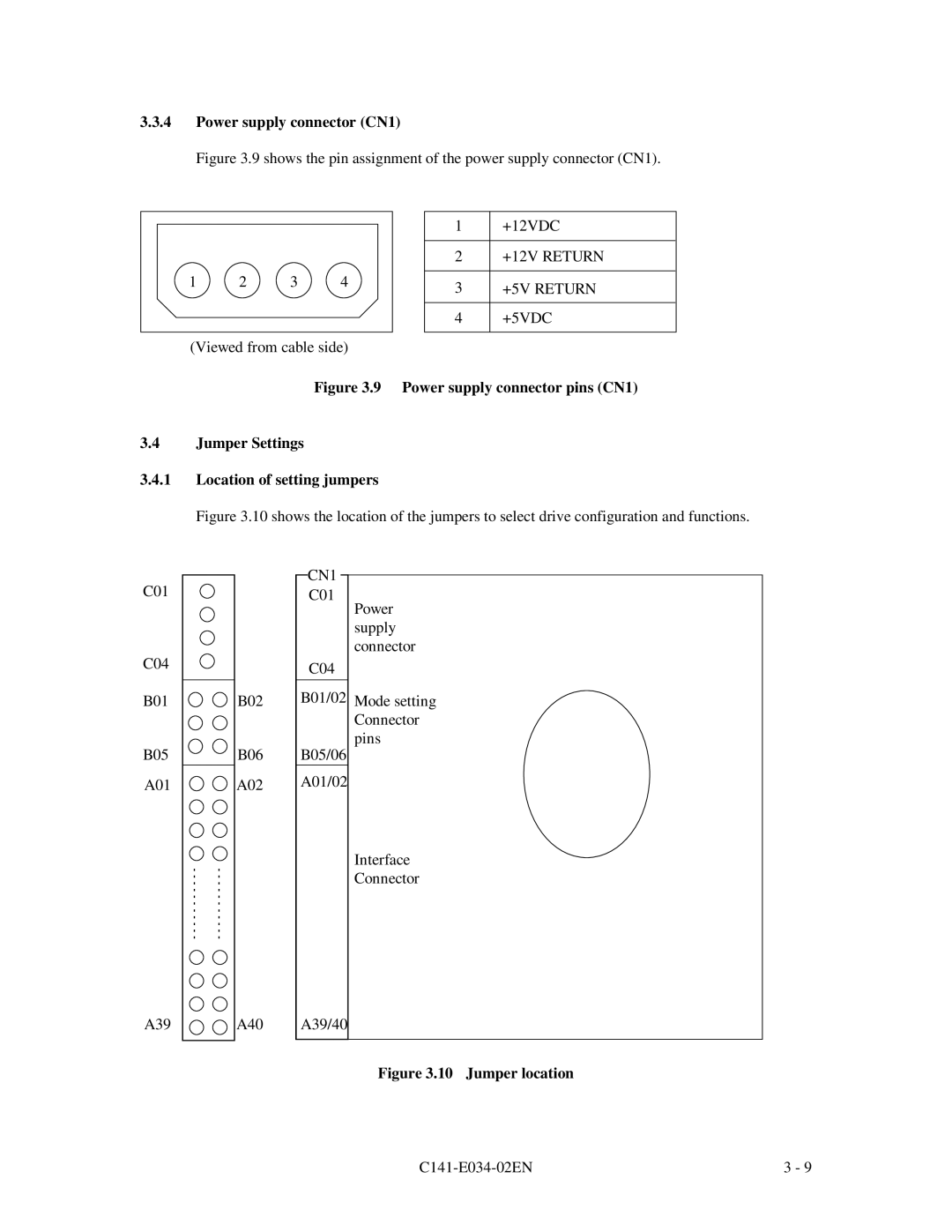
Figure 3.9 shows the pin assignment of the power supply connector (CN1).
1 | 2 | 3 | 4 |
(Viewed from cable side)
1+12VDC
2+12V RETURN
3+5V RETURN
4+5VDC
Figure 3.9 Power supply connector pins (CN1)
3.4Jumper Settings
3.4.1Location of setting jumpers
Figure 3.10 shows the location of the jumpers to select drive configuration and functions.
C01
C04
B01
B05
A01
B02
B06
A02
CN1
C01
Power supply connector
C04
B01/02 Mode setting Connector pins
B05/06
A01/02
Interface Connector
A39
A40
A39/40
Figure 3.10 Jumper location
3 - 9 |