Digital Multifunction Power Monitors
EPM 5200, 5300
Page
Table of Contents
REFERENCE………………81
SET LIMITS/RELAYS
Mode
Chapter AC Power Measurement
Single Phase System
Three-Phase System
Relationship between apparent, real Reactive power
Consumption, Demand and Poor Power Factor
Poly Phase System 1 Delta, 2 Wye
Total Harmonic Distortion THD
Waveform and Harmonics
Sinusoidal Waveform a sin ω ⋅ t
Chapter Mechanical Installation
Diagram 2.1 Standard installation
Port
CT Connection
Chapter Electrical Installation
Connecting the Current Circuit
Helpful Debugging Tools
Electrical Connection Installation
Connecting the Voltage Circuit
Connection to the Main Power Supply
Control Power Option Suffix Current
List of Connection Diagrams
2L1
Line Back View
IV. Three-Phase Four-Wire Wye with Direct Voltage and CTs
Three Phase Four-Wire Wye with CT and PTs
Load
VI. Single Phase with CT and PT Connection
EPM 5300P-S
VII. Dual-Phase with CTs and PTs
VIII. Three-Phase Four-Wire WYE with 2.5 Element
Relays & 1 KYZ Pulse Output -NL Option
Relay, Protection and Pulse Output
EPM 5300P Relay Overview
KYZ Pulse Outputs NL2 Option
Decimal Point Placement Change in Level KW/MW
Standard Rate Table for Watts
Voltage
9999.0 Units W Hour 999.9 99.99
KYZ Relay Connection for -NL2 Option
RS-485
Chapter Communication Installation
RS-232C
Connection for DB-9 Female
RS-485 Hookup Diagram 2 wire Half Duplex
RS-485 Hookup Diagram 2 wire Half Duplex Closed Loop
RS-485 Hookup Diagram 2 wire Half Duplex Detail View
RS-485 Hookup Diagram 4 wire Full Duplex
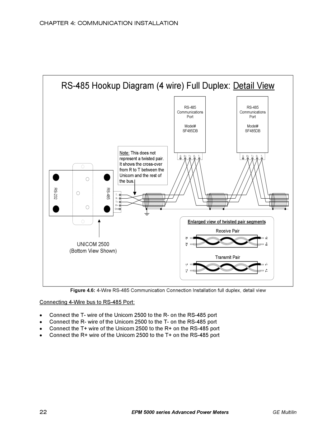
RS-485 Hookup Diagram 4 wire Full Duplex Detail View
Bottom View Shown
Network of Instruments and Long Distance Communication
Computer
Modem Connected to Computer Originate Modem
Programming the Modem
Debugging Communication Problems
Communication Installation
Power A, B, C
Chapter Overview
Accessing %THD Functions
Accessing the Power Functions
Accessing Voltage and Current Phases
Viewing Individual Phase Indication for Power Functions
Step
Resetting Values
Unprotected Reset
Protected Reset
Resetting Hour Readings
Accessing the LM1/LM2 Set Limits
This display Press and hold down
Voltage Phase Reversal and Imbalance
Phase Reversal Phase Imbalance
Indicates a Voltage
Print Operating Data
Access Modes
Appears, confirming a successful print command
Press and hold Press Amps until a Appears
Print Programming Data
Accessing Firmware Version/LED Test
Step Press and hold PHASE/NEXT Press Amps until 4 appears
Step
Chapter Programming Overview
General Procedure
Switch Packs
Groups Functions Packs
Programming Mode Data Entry
Standard Numeric Data Entry
Chapter
EPM 5200P
5300P 5200P 5350P
Feature 5300P 5200P 5350P
EPM 5300P vs. EPM 5200P vs. EPM 5350P
Password Entry
Chapter Entering Programming Mode
Checksum Error-Protective Self-Checking Algorithms
Entering Programming Mode
Entering Programming Mode
Function
Chapter Programming Group 0 Global Meter Setup
Group 0, Function 0-The Integration Interval
Function
Group 0, Function 1-The Meter Address
Group 0, Function 2-BAUD Rate
Group 0, Function 3-System Configuration
Group Function Pack
Pack Switch Feature Segment Position
Down +PF
Printing Option
Open Delta System Installation Programming
Modbus Plus Capability
Disabling Prevents
Group 0, Function 3-Programming Procedure
To change the System Configuration Switch Settings
Switch C Description
Relay Mode
Switch Description
Definitions
04.P Controls Relay 05.P Controls Relay 2 and 3 if NL4
Programming Steps
Group 0-FUNCTION Number Description
To change the Relay Mode to either Fail-safe or Reset
Group and Function Number Description
To change Time Delays
To program Relay
Group 0, Function 6-KYZ Parameter Selection
Parameter Description
Value PER PER Watt Hour
Selection KYZ Pulse KYZ Pulse Value
06P
FSW=9.999
Situation 3 FSW=99.99
Situation 4 FSW=9.999
Group 0, Function 7-Number of Phases
Standard Factory SET-UP is THREE-PHASE FOUR-WIRE
Formulas
Group and Function Number
To change the Full Scale Settings
Voltage Full Scale
Press Volts to move decimal point Press Amps to store
Group 1, Function 1-Amperage Full Scale
CT T YPE Full Scale
Step Press Amps to begin Data Entry Sequence
Example 3 14.4 KV/120, 1000/5 CT
FSV=480 FSA=1000 a FSW one phase=480 V ⋅ 1000 a
Example 2 480/120 PT, 1000/5 CT
FSV=14.40 KV FSA=1000 a
To change the scale factor setting for wattage
Programming Group
High End Calibration-Volts AN, BN, CN
Chapter Programming Group 2-METER Calibration
Calibration Requirements
High End Calibration-Amps A, B, C
Voltage Range Input Source Group 2 Value
To change the calibration high end-Functions 0
For Amps Low End Function
Press MAX/MIN/LIMITS to end calibration procedure
Example of LM1/LM2 SET Limits
Time Delays & Relay Mode
Chapter Groups 4, 5 and 6-SET Limits and Relays
Trip Relay
Group 4, Functions 0-3-LM1/LM2 Set Limits
Group 4 Programming Format for Limit Condition
Group 5, Functions 0-7-LM1/LM2 Set Limits
There are 3 Switches to SET with Limits
Digit Up Digit Down 0120
LM1 LM2 Switch Value LED ABOVE/BELOW Relay
Programming Group 6, LM1/LM2 Set Limits
Digit Up Digit Down 012.0
Limits or Relays Programming Procedure
LM1 LED LM2 LED Switch Level ABOVE/BELOW Relay
Digit Down Digit Up 009.0
Press Amps once to Disable the Limit
Follow this step for Disabling Limits
See to Exit
Phase Reversal and Phase Imbalance
∃TRIP Relay 1 %TRIP Relay 2 &LEVEL ∋ENABLE/DISABLE
Voltage Phase Imbalance
Group 7, Function 0-Voltage Phase Reversal Detection
Voltage Phase Reversal Detection
To change the phase reversal setting
Group 7, Function 1-Percentage Voltage Phase Imbalance
To change the percentage voltage phase imbalance
See to Exit
Chapter Exiting Programming Mode
Exiting Programming Mode
Data Entry Sequence
Entering the Programming Mode
Chapter Programming Quick Reference
Programming Groups
Group 0-Global Meter Setup
Reserved Switches
Group 3 Calibration Ratios
Group 1 Full Scale Setup
Group 2 Calibration
Group 4 Volt/Current Limits
Group 7 Imbalance/Reversal Limits
Group 5 Power Function Limits
Group 6 THD Limits
Group 8 DC output Calibration
KEY Designations
Programming Quick Reference
Chapter Ethernet Option
Ethernet Module
Ethernet Option Setup
Description LED Functions
Network Port Login
Default IP Address
Setting the IP Address
AutoIP
Telnet to Port
Network Configuration
ARP on Windows
Configuration Parameters
Baud Rate
GE Multilin