Instruction Manual
DIGITAL MULTIFUNCTION POWER MONITORS
GEK-106557A Copyright 2004 GE Multilin
EPM 5200, 5300
Page
INSTALLATION
TABLE OF CONTENTS
INSTALLATION
INSTALLATION
MODE
16.2 Ethernet Option Setup
SET LIMITS/RELAYS
REFERENCE………………81
CHAPTER AC POWER MEASUREMENT
1.1 Single Phase System
W 2 + VAR
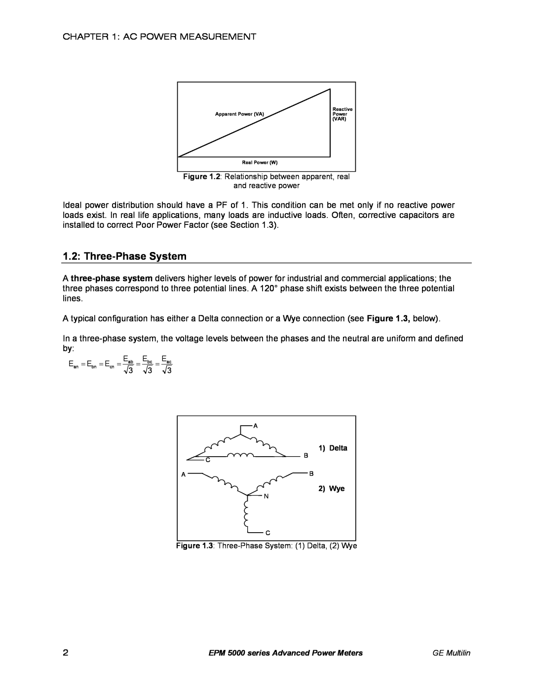
Figure 1.3 Three-Phase System 1 Delta, 2 Wye
1.2 Three-Phase System
Figure 1.2 Relationship between apparent, real and reactive power
3 3
1.3 Consumption, Demand and Poor Power Factor
1 Delta
2 Wye
1.4 Waveform and Harmonics
THD GRAPH
GE Multilin
CHAPTER MECHANICAL INSTALLATION
EPM 5000 series Advanced Power Meters
4.50
W Port
EPM 5000 series Advanced Power Meters
CONNECTOR TOGETHER
GE Multilin
3.2 CT Connection
CHAPTER ELECTRICAL INSTALLATION
3.1 Connecting the Current Circuit
HELPFUL DEBUGGING TOOLS
3.6 Electrical Connection Installation
3.3 Connecting the Voltage Circuit
3.5 Connection to the Main Power Supply
3.4 Selecting the Voltage Fuses
LIST OF CONNECTION DIAGRAMS
I. Three Phase, Three-Wire System Delta with Direct Voltage and CTs
II. Three-Phase, Three-Wire Open Delta with two CTs and two PTs
EPM 5000 series Advanced Power Meters
IV. Three-Phase Four-Wire Wye with Direct Voltage and CTs
V. Three Phase Four-Wire Wye with CT and PTs
POWER
VI. Single Phase with CT and PT Connection
The EPM 5300P-S
PORT
EPM 5000 series Advanced Power Meters
VII. Dual-Phase with CTs and PTs
VIII. Three-Phase Four-Wire WYE with 2.5 Element
POWER
2 RELAYS & 1 KYZ PULSE OUTPUT -NL OPTION
3.7 Relay, Protection and Pulse Output
EPM 5300P RELAY OVERVIEW
This section applies only to the -NL or -NL2 Relay Option
DECIMAL POINT PLACEMENT
STANDARD RATE TABLE FOR WATTS
3.8 KYZ Pulse Outputs NL2 Option
CHANGE IN LEVEL
CHANGE IN LEVEL
DECIMAL POINT PLACEMENT
STANDARD RATE TABLE FOR WATTS
KW/MW
4.2 RS-485
CHAPTER COMMUNICATION INSTALLATION
4.1 RS-232C
RS-232 COMMUNICATION CONNECTION
GE Multilin
RS-485 Hookup Diagram 2 wire Half Duplex
EPM 5000 series Advanced Power Meters
5300P Instruments rear view
GE Multilin
RS-485 Hookup Diagram 2 wire Half Duplex Closed Loop
EPM 5000 series Advanced Power Meters
5300P Instruments rear view RS-485 Communications Port Model #SF485DB
GE Multilin
RS-485 Hookup Diagram 2 wire Half Duplex Detail View
EPM 5000 series Advanced Power Meters
UNICOM
RS-485 Hookup Diagram 4 wire Full Duplex
RS-485 Communications Port Model#SF485DB
UNICOM Bottom View Shown
RS-485 Hookup Diagram 4 wire Full Duplex Detail View
Enlarged view of twisted pair segments
4.3 Network of Instruments and Long Distance Communication
I. MODEM CONNECTED TO COMPUTER ORIGINATE MODEM Programming the Modem
II. MODEM CONNECTED TO THE DEVICE REMOTE MODEM Programming the Modem
YOU MAY WANT TO USE A MODEM MANAGER RS485-RS232 CONVERTER
Debugging Communication Problems
CHAPTER 4 COMMUNICATION INSTALLATION
EPM 5000 series Advanced Power Meters
GE Multilin
CHAPTER OVERVIEW
POWER A, B, C
5.3 Accessing %THD Functions
5.1 Accessing the Power Functions
5.2 Accessing Voltage and Current Phases
a. Press POWER to select the power category
Step
5.4 Viewing Individual Phase Indication for Power Functions
To access %THD
Step
a. Press PHASE/NEXT for the desired phase
EPM 5000 series Advanced Power Meters
5.6 Resetting Values
Step
a. Press MAX/MIN/LIMITS twice to access the min value for Amps A
UNPROTECTED RESET
PROTECTED RESET
a. Press PHASE/NEXT
b. Press PHASE/NEXT
5.7 Resetting Hour Readings
5.8 Accessing the LM1/LM2 Set Limits
press PHASE/NEXT. A
PHASE/NEXT. While
5.9 Voltage Phase Reversal and Imbalance
a. Press PHASE/NEXT
Phase Reversal
PHASE/NEXT
5.10 Access Modes
5.11 Print Operating Data
b. Press PHASE/ NEXT to
PHASE/NEXT
5.13 Accessing Firmware Version/LED Test
5.12 Print Programming Data
b. Press PHASE/NEXT to
Step
Step
GROUPS, Functions, and Switch PACKS
61 General Procedure
6.2 Switch Packs
CHAPTER PROGRAMMING OVERVIEW
6.3 Programming Mode Data Entry
6.4 Standard Numeric Data Entry
CHAPTER EPM 5200P
5300P
EPM 5300P vs. EPM 5200P vs. EPM 5350P
Feature
5200P
8.2 Password Entry
CHAPTER ENTERING PROGRAMMING MODE
8.1 Checksum Error-Protective Self-Checking Algorithms
Entering Programming Mode
CHAPTER 8 ENTERING PROGRAMMING MODE
EPM 5000 series Advanced Power Meters
GE Multilin
FUNCTION
CHAPTER PROGRAMMING GROUP 0 - GLOBAL METER SETUP
9.1 Group 0, Function 0-The Integration Interval
Function
See Chapter 14 to Exit
9.2 Group 0, Function 1-The Meter Address
EPM 5000 series Advanced Power Meters
GE Multilin
EPM 5000 series Advanced Power Meters
9.3 Group 0, Function 2-BAUD RATE
CHAPTER 9 PROGRAMMING GROUP 0 - GLOBAL METER SETUP
To change the Baud Rate
FUNCTION
9.4 Group 0, Function 3-System Configuration
GROUP
PACK
PACK
SWITCH
FEATURE
SEGMENT POSITION
9.5 Modbus Plus Capability
OPEN DELTA SYSTEM INSTALLATION PROGRAMMING
SWITCHING COMMUNICATION PROTOCOLS, EI-BUS, MODBUS RTU/ASCII, DNP
PRINTING OPTION
EPM 5000 series Advanced Power Meters
9.6 Group 0, Function 3-Programming Procedure
This example shows enabling of Open Delta Installation switch
See Chapter 14 to Exit
SWITCH
9.7 Relay Mode
DEFINITIONS
SWITCH C
R E S E T
PROGRAMMING STEPS
NOTE Under this setup the relay will NOT act as a protective switch
PROGRAMMING STEPS
EPM 5000 series Advanced Power Meters
CHAPTER 9 PROGRAMMING GROUP 0 - GLOBAL METER SETUP
To change the Relay Mode to either Fail-safe or Reset
Step
Relay 1 Off to On Delay Time
9.8 Group 0, Functions 4-5-Time Delay for Relays 1 and 2 Option - NL
Relay 1 On to Off Delay Time
Relay 2 On to Off Delay Time
GE Multilin
EPM 5000 series Advanced Power Meters
See Chapter 14 to Exit
a. Press MAX/MIN/LIMITS until Function 04.P appears
PARAMETER
9.9 Group 0, Function 6-KYZ Parameter Selection
NOTE FUNCTION 6 applies only if Option -NL or -NL2 was ordered
DESCRIPTION
KYZ PULSE
The FSW number is used only for decimal point placement see Chapter
SELECTION
KYZ PULSE
S ITUATION 1 FSW=9999
HOW TO USE KYZ PULSE VALUE TABLE FOR MULTIPLICATION
HOW TO USE THE KYZ PULSE VALUE TABLE FOR DIVISION
S ITUATION 2 FSW=999.9
EPM 5000 series Advanced Power Meters
9.10 Group 0, Function 7-Number of Phases
STANDARD FACTORY SET-UP IS THREE-PHASE FOUR-WIRE
NOTE ENTER 1 FOR SINGLE PHASE/SINGLE WIRE
GROUP AND FUNCTION NUMBER
CHAPTER PROGRAMMING GROUP 1 - VOLTAGE, AMP AND WATT SCALE SETTINGS
FORMULAS
FUNCTION
VOLTAGE FULL SCALE
GE Multilin
EPM 5000 series Advanced Power Meters
CHAPTER 10 PROGRAMMING GROUP
ENTERING THE SCALE FACTOR
10.2 Group 1, Function 1-Amperage Full Scale
CT T YPE
FULL SCALE
a. Press VOLTS to move decimal point
EPM 5000 series Advanced Power Meters
GE Multilin
Group and Function Number appear including a
FSW one phase=480,000 W FSW three phase=480,000 W ⋅ 3 = 1,440,000 W
FSW one phase =120 Vx5.00 A FSW one phase=600 W
FSW three phase=600 Wx3 = 1,800 W
FSW one phase=14,400 Vx1000 A FSW one phase=14,400,000 W
CHAPTER 10 PROGRAMMING GROUP
To change the scale factor setting for wattage
EPM 5000 series Advanced Power Meters
Step
EPM 5000 series Advanced Power Meters
CHAPTER 10 PROGRAMMING GROUP
GE Multilin
CHAPTER PROGRAMMING GROUP 2-METER CALIBRATION
11.1 Calibration Requirements
WARNING-READ THIS SECTION CAREFULLY BEFORE PROCEEDING
VOLTAGE RANGE
INPUT SOURCE
GROUP 2 VALUE
For Amps Low End Function
EPM 5000 series Advanced Power Meters
CHAPTER 11 PROGRAMMING GROUP 2 - METER CALIBRATION
Step
New value moves to middle display
c. Press MAX/MIN/LIMITS to end calibration procedure
EPM 5000 series Advanced Power Meters
See Chapter 14 to Exit
EXAMPLE OF LM1/LM2 SET LIMITS
12.2 Time Delays & Relay Mode
CHAPTER GROUPS 4, 5 AND 6-SET LIMITS AND RELAYS
12.1 Trip Relay
LM1/LM2 Set Limits for Volts AN, BN, CN
12.3 Group 4, Functions 0-3-LM1/LM2 Set Limits
Group 4 Programming Format for Limit Condition
LM1/LM2 Set Limits for Volts AB, BC, CA
RELAY
12.4 Group 5, Functions 0-7-LM1/LM2 Set Limits
SPECIAL CASES
THERE ARE 3 SWITCHES TO SET WITH LIMITS
SWITCH
Programming Group 6, LM1/LM2 Set Limits
SWITCH
SWITCH
SWITCH
12.6 Limits or Relays Programming Procedure
SWITCH
SWITCH
EPM 5000 series Advanced Power Meters
The display blanks momentarily, then the disabled settings appears in middle and lower displays
GE Multilin
See Chapter 14 to Exit
EPM 5000 series Advanced Power Meters
a. Press VOLTS to scroll through digits b. Press AMPS to select
GE Multilin
FIGURE 13-1 EXAMPLE OF SET LIMITS
CHAPTER PHASE REVERSAL AND PHASE IMBALANCE SET LIMITS/RELAYS
13.1 Phase Reversal and Phase Imbalance
13.2 Trip Relay
Voltage Phase Imbalance
13.3 Group 7, Function 0-Voltage Phase Reversal Detection
Voltage Phase Reversal Detection
EPM 5000 series Advanced Power Meters
To change the percentage voltage phase imbalance
13.4 Group 7, Function 1-Percentage Voltage Phase Imbalance
CHAPTER 13 PHASE REVERSAL AND PHASE IMBALANCE SET RELAYS
EPM 5000 series Advanced Power Meters
See Chapter 14 to Exit
CHAPTER 14 EXITING PROGRAMMING MODE
EPM 5000 series Advanced Power Meters
GE Multilin
CHAPTER EXITING PROGRAMMING MODE
5300P Advanced Power Meter
GE Industrial Systems
CHAPTER 14 EXITING PROGRAMMING MODE
EPM 5000 series Advanced Power Meters
GE Multilin
15.2 Data Entry Sequence
15.1 Entering the Programming Mode
CHAPTER PROGRAMMING QUICK REFERENCE
15.3 Programming Groups
15.4 Group 0-Global Meter Setup
030. Reserved Switches
B. Reserved
15.7 Group 3 Calibration Ratios
15.5 Group 1 Full Scale Setup
15.6 Group 2 Calibration
15.8 Group 4 Volt/Current Limits
15.11 Group 7 Imbalance/Reversal Limits
15.9 Group 5 Power Function Limits
15.10 Group 6 THD Limits
15.12 Group 8 DC output Calibration
MAX/MIN/LIMITS
KEY DESIGNATIONS
C. Reserved D. Reserved 80. DC output Port
VOLTS
EPM 5000 series Advanced Power Meters
CHAPTER 15 PROGRAMMING QUICK REFERENCE
GE Multilin
CHAPTER ETHERNET OPTION
16.1 Ethernet Module
ETHERNET 10 BASE T RJ-45
16.2 Ethernet Option Setup
Description
LED Functions
16.4 AutoIP
16.3 Default IP Address
16.5 Setting the IP Address
NETWORK PORT LOGIN
TELNET TO PORT
16.6 Network Configuration
ARP ON WINDOWS
TELNET TO PORT
16.7 Configuration Parameters
BAUD RATE
GE Multilin

 3
3  3
3  3
3