Installation Instructions

EXHAUSTING THE DRYER

WARNING – To reduce the risk of fire or personal injury:

This clothes dryer must be exhausted to the outdoors.

Use only 4″ rigid metal ducting for the home exhaust duct.

Use only 4″ rigid metal or UL-listed flexible metal (semi-rigid or foil-type) duct to connect the dryer to the home exhaust duct. It must be installed in accordance with the instructions found in “Connecting the Dryer to House Vent” on page 25 of this manual.

Do not terminate exhaust in a chimney, a wall, a ceiling, gas vent, crawl space, attic, under an enclosed floor, or in any other concealed space of a building.

Never terminate the exhaust into a common duct with a kitchen exhaust system. A combination of grease and lint creates a potential fire hazard.

Do not use duct longer than specified in the exhaust length table. Longer ducts can accumulate lint, creating a potential fire hazard.

Never install a screen in or over the exhaust duct. This will cause lint to accumulate, creating a potential fire hazard.

Do not assemble ductwork with any fasteners that extend into the duct. These fasteners can accumulate lint, creating a potential fire hazard.

Do not obstruct incoming or exhausted air.

Provide an access for inspection and cleaning of the exhaust system, especially at turns and joints. Exhaust system shall be inspected and cleaned at least once a year.

This dryer comes ready for rear exhausting. If space is limited, use the instructions on pages 28–30 to exhaust directly from the sides or bottom of the cabinet.

EXHAUST SYSTEM CHECKLIST

HOOD OR WALL CAP

Terminate in a manner to prevent back drafts or entry of birds or other wildlife.

Termination should present minimal resistance to the exhaust airflow and should require little or no maintenance to prevent clogging.

Never install a screen in or over the exhaust duct.

Wall caps must be installed at least 12″ above ground level or any other obstruction with the opening pointed down.

SEPARATION OF TURNS

For best performance, separate all turns by

at least 4 ft. of straight duct, including distance between last turn and dampened wall cap.

SEALING OF JOINTS

All joints should be tight to avoid leaks. The male end of each section of duct must point away from the dryer.

Do not assemble the ductwork with fasteners that extend into the duct. They will serve as a collection point for lint.

Duct joints should be made air- and moisture-tight by wrapping the overlapped joints with duct tape or aluminum tape.

Horizontal runsshould slope down towards the outdoors 1/4 per foot.

INSULATION

Ductwork that runs through an unheated area or is near air conditioning should be insulated to reduce condensation and lint buildup.

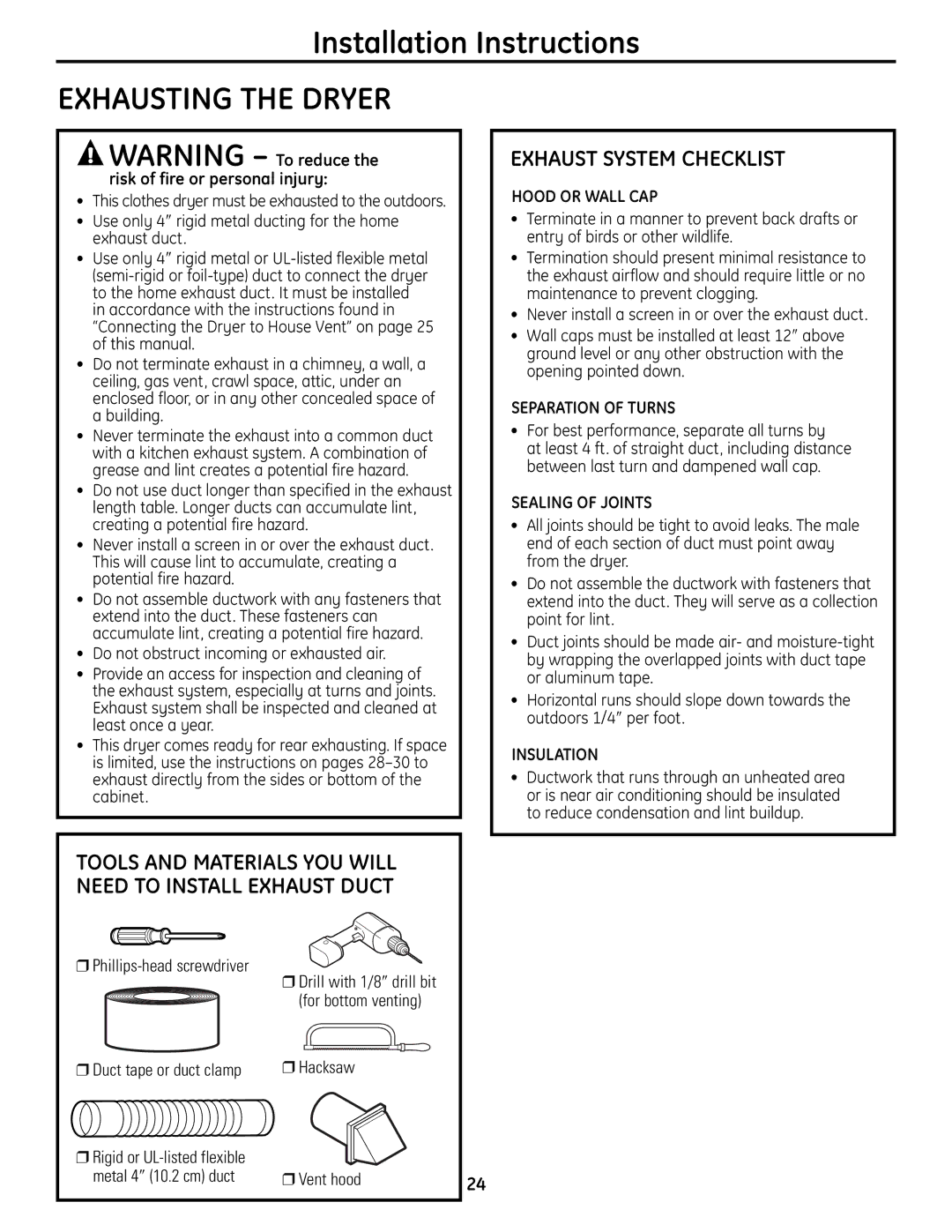
TOOLS AND MATERIALS YOU WILL NEED TO INSTALL EXHAUST DUCT

Phillips-head screwdriver

Drill with 1/8″ drill bit


(for bottom venting)

Duct tape or duct clamp

Hacksaw

Rigid or UL-listed flexible


metal 4″ (10.2 cm) duct

Vent hood

24


Page 24
Image 24
GE UPVH890 Exhausting the Dryer, Exhaust System Checklist, Tools and Materials YOU will Need to Install Exhaust Duct

UPVH890 specifications

The GE UPVH890 is a state-of-the-art ultrasound machine that redefines imaging capabilities in the medical field. It is designed for comprehensive diagnostic applications, emphasizing portability, versatility, and advanced imaging technologies. This device stands at the intersection of functionality and user-friendliness, making it a valuable asset in various healthcare settings, from hospitals to outpatient clinics.

One of the main features of the UPVH890 is its lightweight design. Weighing significantly less than traditional ultrasound machines, it offers unparalleled portability, allowing healthcare providers to transport it easily from room to room or even to remote locations. This is particularly advantageous in emergency situations where rapid ultrasound assessments are crucial.

The UPVH890 employs cutting-edge imaging technologies, including advanced three-dimensional and four-dimensional imaging capabilities. These features enable clinicians to visualize complex anatomical structures in real-time, enhancing diagnostic accuracy. The system is equipped with enhanced Doppler imaging, crucial for evaluating blood flow, and provides high-resolution images that aid in better assessment of conditions.

Additionally, the device incorporates artificial intelligence (AI) algorithms, which streamline the workflow and improve image interpretation. The built-in AI assists clinicians by providing automated measurements and suggesting the most likely diagnosis based on the obtained data, ultimately leading to quicker and more accurate patient care.

The UPVH890 also boasts an intuitive touchscreen interface that facilitates easy navigation through various settings and functions. This feature reduces the learning curve for new users and enhances efficiency for experienced operators. The customizable user interface allows healthcare providers to tailor the machine's settings according to their specific preferences and the needs of their patients.

In terms of connectivity, the UPVH890 supports wireless communication, enabling seamless integration with electronic medical record (EMR) systems. This capability ensures that patient information is readily available, promoting coordinated care and efficient follow-up processes.

Overall, the GE UPVH890 ultrasound machine stands out for its innovative features, intelligent technologies, and user-centric design that collectively enhance diagnostic efficiency and patient care. It represents a significant advancement in the field of medical imaging, catering to a wide range of clinical needs while ensuring ease of use and accessibility.