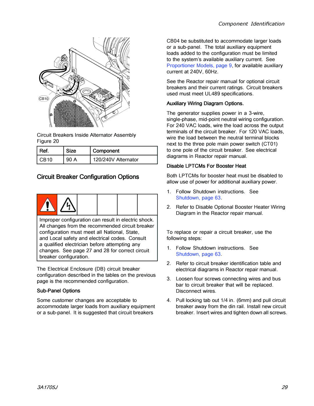
CB10
Circuit Breakers Inside Alternator Assembly Figure 20
Ref. | Size | Component |
CB10 | 90 A | 120/240V Alternator |
Circuit Breaker Configuration Options
Improper configuration can result in electric shock. All changes from the recommended circuit breaker configuration must meet all National, State,
and Local safety and electrical codes. Consult a qualified electrician before attempting any changes. See page 27 and 28 for correct circuit breaker configuration.
The Electrical Enclosure (DB) circuit breaker configuration described in the tables on the previous page is the recommended configuration.
Sub-Panel Options
Some customer changes are acceptable to accommodate larger loads from auxiliary equipment or a
Component Identification
CB04 be substituted to accommodate larger loads or a
See the Reactor repair manual for optional circuit breakers and their current ratings. Circuit breakers used must meet UL489 specifications.
Auxiliary Wiring Diagram Options.
The generator supplies power in a
Disable LPTCMs For Booster Heat
Both LPTCMs for booster heat must be disabled to allow use of power for additional auxiliary power.
1.Follow Shutdown instructions. See Shutdown, page 63.
2.Refer to Disable Optional Booster Heater Wiring Diagram in the Reactor repair manual.
To replace or repair a circuit breaker, use the following steps:
1.Follow Shutdown instructions. See Shutdown, page 63.
2.Refer to circuit breaker identification table and electrical diagrams in Reactor repair manual.
3.Loosen four screws connecting wires and bus bar to circuit breaker that will be replaced. Disconnect wires.
4.Pull locking tab out 1/4 in. (6mm) and pull circuit breaker away from the din rail. Install new circuit breaker. Insert wires and tighten down all screws.
3A1705J | 29 |