Instructions
Important Safety Instructions
Contents
Electric Shock Hazard
Skin Injection Hazard
Pressurized Aluminum Hazard
Battery Hazard
Isocyanate Conditions
Important Two-Component Material Information
Material Self-Ignition
Moisture Sensitivity of Isocyanates
Changing Materials
Foam Resins with 245 fa Blowing Agents
Proportioner Models
30i Series
XP2i Series
Approvals
Systems
Systems with Air Compressor
Accessories
Related Manuals
Supplied Manuals
Typical Installation, with circulation
Typical Installation, without circulation
Component Identification
GG Generator,
Proportioner Control Panel,
MM Motor Control Module MCM,
High Power Temperature Control Module
Generator
Air Compressor
Proportioner Control Panel
Advanced Display Module ADM,
Engine Control Module,
Call Button Function Out
Advanced Display Module ADM
Red Random Flashing or Solid Module error exists
System Status Indicator B Conditions
USB Module Status LEDs CL Conditions
Module Status LEDs CN Conditions
Menu Bar
Power Up Screen
Soft Keys
Navigation within Screens
Icons
See Errors, page 51 for more
Icons Function
Softkeys Icon Function
Motor Control Module MCM
MCM Rotary Switch Positions
Icon Description Function
Engine Control Module
Load Center
Related Component
Color
Temperature Control Modules
Low Power Module Lptcm Cable Connections
Advanced Display Module ADM, page 19, CN for conditions
Hptcm a and B Rotary Switch Settings
Adjust Rotary Switch
Setting Zone
Lptcm a and B Rotary Switch Settings
Size Component
Circuit Breakers
MCM
See Circuit Breaker Configuration Options,
Disable LPTCMs For Booster Heat
Auxiliary Wiring Diagram Options
Circuit Breaker Configuration Options
Size Component CB10 90 a 120/240V Alternator
Overview
Overview
HE VB HE VA
Setup
Trailer Setup Guidelines, page 35 for instructions
Locate Reactor
Setup
Trailer Setup Guidelines
Install Wall optional
Top View With Wall Side View With Wall
Connect Battery
Add Fuel
General Equipment Guidelines
Electrical Connections
Connect Feed Pumps
Breathing Air
Install Fluid Temperature Sensor
Connect Pressure Relief Lines
Connect Heated Hose
Pressure Check Hose
Connect Whip Hose to Gun Or Gun Fluid Manifold
Connect Remote Display Module
Grounding
Supply Wet Cups With Throat Seal Liquid TSL
Advanced Screen 3- USB,
Advanced Display Module ADM Operation
Set Password
Setup Mode
Setup Screens Navigation Diagram Figure
Advanced Screen 1 General
Advanced Setup Screens
Advanced Screen 3 USB
Advanced Screen 2 Units
System
Enable or Disable Recipes
Recipes
Add Recipe
Run Mode
Run Screens Navigation Diagram
Home System Off
Home System With Error
Home System Active
Targets
Errors
Maintenance
Cycles
Events
Diagnostic
Recipes
Troubleshooting
System Events
Startup
Check coolant color
Open the main air shutoff valve
Load fluid with feed pumps
Setup ADM. Advanced Display Module ADM Operation,
Temporary Manual Hose Temperature Control
Fluid Circulation
Circulation Through Reactor
Follow Startup,
Jog Mode
Circulation Through Gun Manifold
Gun Manual
Fusion AP gun is shown
Spraying
Spray Adjustments
Shutdown
Pressure Relief Procedure,
Pressure Relief Procedure
Flushing
Flushing
Proportioner Maintenance
Maintenance
Every 500 Service Hours or 1 Year
Engine Maintenance
Fuel Tank
Flush Inlet Strainer Screen
Pump Lubrication System
Follow Pressure Relief Procedure,
Perform Shutdown,
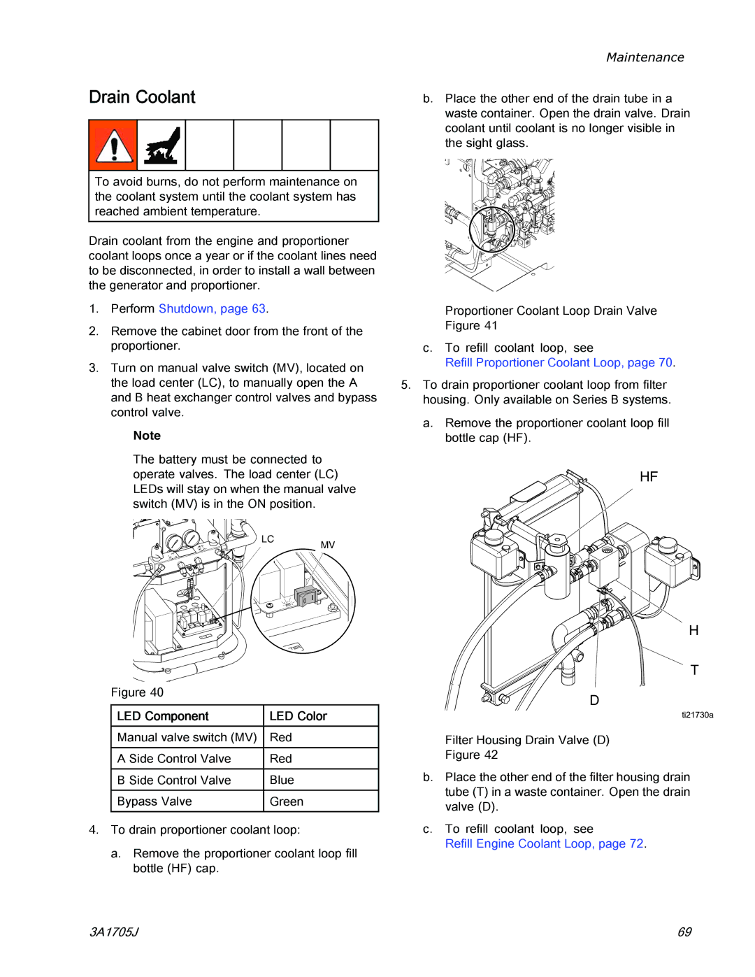
Drain Coolant
Refill Proportioner Coolant Loop,
LED Component LED Color
Refill Proportioner Coolant Loop
Maintenance
Coolant Specifications
Refill Engine Coolant Loop
Errors
View Errors
Troubleshoot Errors
Error Codes and Troubleshooting
Troubleshooting
Error Type Name Cause Solution Code Location
A1NM MCM Alarm
A4CH
A4CM MCM Alarm
A4DA
A4DB
A7CH
A4NM MCM Alarm
A7DA
A7DB
Cacb
Caca
Cach
Cacm MCM
DE0X MCM Alarm
Dadx MCM Alarm
F9DX MCM Alarm
K8NM MCM Alarm
P6AX MCM Alarm
P4AX MCM Alarm
MBN0 MCM Advi
Sory
Error Type Name Cause Solution Code Position
T2AE
Deviation
T2BE
T2DB
T2DA
T2DH
T2DE
T4CA
T4CM MCM Alarm
T4CB
T4CH
T4DH
T4NM MCM Alarm
T6BE
T6AE
T6DA
T6DB
T8AE
V4CM MCM Alarm
V1CM MCM Alarm
Wbnm MCM Alarm
T8DA
MCM Alarm
Wmce MCM Alarm
Wscx ADM Advisory
Wsux USB Advisory
USB Data
Follow Download Procedure, page 91, to retrieve log files
USB Logs
Event Log
Daily Log
System Configuration Settings
System Software Log
Blackbox Log File
Custom Language File
Download Procedure
Create Custom Language Strings
Upload Procedure
Information Screens
Appendix a Engine Control Module Run Screens
Run Screen Layout
Information Screen Layout
Mode Icons
Instrumentation Icons
Icon Description Details
Shutdown
Alarms
Dimensions
Dimensions
Pallet Mounting Dimensions
Proportioners For Foam
Performance Charts
Proportioners For Coatings
Pressure
Fusion Mechanical Purge, Round Pattern
Fusion Air Purge, Flat Pattern
Fusion Mechanical Purge, Flat Pattern
30i Models
Technical Specifications
Recommended Air Compressors
Weight
Noise
Fluid Inlets
XP2i Models
3A1705J 105
Graco Standard Warranty
Graco Information
For Graco Canada Customers