Setup Mode
1.See FIG. 31. Press and hold ![]() for 5 seconds until Setup menu appears.
for 5 seconds until Setup menu appears.
2.To enter settings for runaway, lower size, and flow rate units, and to enable runaway, E1, E2, and E5
error options, press ![]() to change the value, then
to change the value, then
![]() to save the value and move the cursor to the next data field. See page for a description of E1, E2, and E5 error codes.
to save the value and move the cursor to the next data field. See page for a description of E1, E2, and E5 error codes.
Operation
NOTE: When runaway, E1, E2, and E5 error options are enabled, a ✓ will appear on the setup screen. See FIG. 31.
3.Move the cursor to the E5 error enable option field,
then press ![]() once more to exit Setup mode.
once more to exit Setup mode.
Run Mode
Runaway Monitor
1.See FIG. 31. If pump runaway occurs, the runaway solenoid will actuate, stopping the pump. The LED (CD) will flash and the display (CF) will indicate a runaway condition (see Table 1). The display will cycle through six instruction screens.
2.Runaway Screens 1 and 2: To reset the runaway solenoid, close the master air valve (AP). Wait for air to completely bleed off the air motor.
AP
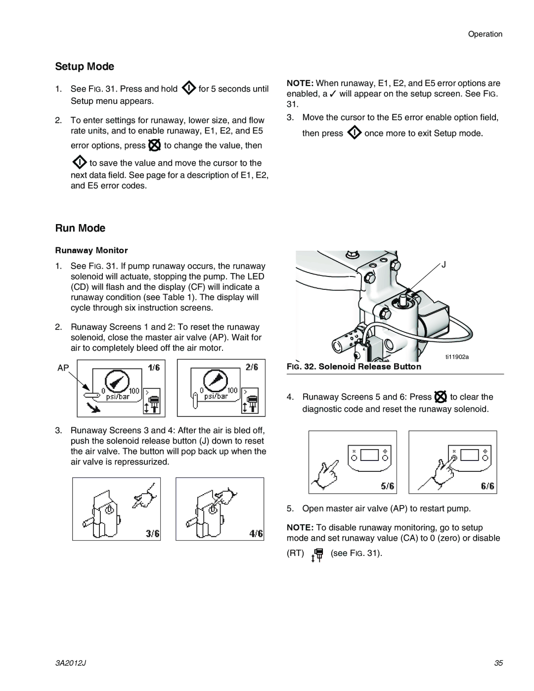
3.Runaway Screens 3 and 4: After the air is bled off, push the solenoid release button (J) down to reset the air valve. The button will pop back up when the air valve is repressurized.
J
ti11902a
FIG. 32. Solenoid Release Button
4.Runaway Screens 5 and 6: Press ![]() to clear the diagnostic code and reset the runaway solenoid.
to clear the diagnostic code and reset the runaway solenoid.
5. Open master air valve (AP) to restart pump.
NOTE: To disable runaway monitoring, go to setup mode and set runaway value (CA) to 0 (zero) or disable
(RT) | (see FIG. 31). |
3A2012J | 35 |