Connect Fluid and Air Lines
Setup
Air Connections
Oil left in the system at the factory can react with cata- lyst and create a fire or explosion.
•Flush before first use.
•Do not add catalyst to the catalyst reservoir until the system has been flushed.
NOTE: When connecting gun hose bundle, the whip end connections in the bundle should be connected to the gun and the
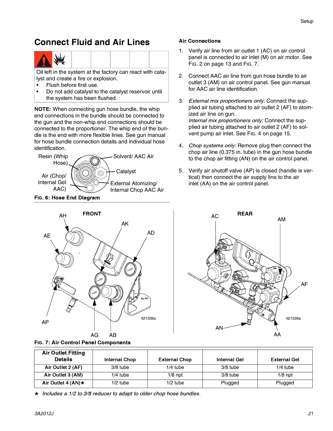
Resin (Whip | Solvent/ AAC Air |
Hose) |
|
Air (Chop/ | Catalyst |
| |
Internal Gel | External Atomizing/ |
AAC) | Internal Chop AAC Air |
FIG. 6: Hose End Diagram |
|
1.Verify air line from air outlet 1 (AC) on air control panel is connected to air inlet (M) on air motor. See FIG. 2 on page 13 and FIG. 7.
2.Connect AAC air line from gun hose bundle to air outlet 3 (AM) on air control panel. See gun manual for AAC air line identification.
3.External mix proportioners only: Connect the sup- plied air tubing attached to air outlet 2 (AF) to atom-
ized air line on gun.
Internal mix proportioners only: Connect the sup- plied air tubing attached to air outlet 2 (AF) to sol- vent pump air inlet. See FIG. 4 on page 15.
4.Chop systems only: Remove plug then connect the chop air line (0.375 in. tube) in the gun hose bundle to the chop air fitting (AN) on the air control panel.
5.Verify air shutoff valve (AP) is closed (handle is ver- tical) then connect the air supply line to the air inlet (AA) on the air control panel.
AH FRONT
AK
AC REAR
AM
AE
AD
AF
ti21338a
AP
AN![]()
ti21339a
AG AB
FIG. 7: Air Control Panel Components
AA
Air Outlet Fitting |
|
|
|
|
Details | Internal Chop | External Chop | Internal Gel | External Gel |
|
|
|
|
|
Air Outlet 2 (AF) | 3/8 tube | 1/4 tube | 3/8 tube | 1/4 tube |
|
|
|
|
|
Air Outlet 3 (AM) | 1/4 tube | 1/8 npt | 3/8 tube | 1/8 npt |
|
|
|
|
|
Air Outlet 4 (AN)★ | 1/2 tube | 1/2 tube | Plugged | Plugged |
|
|
|
|
|
★Includes a 1/2 to 3/8 reducer to adapt to older chop hose bundles.
3A2012J | 21 |