HP 16532A - Performance Tests
4.Set the signal generator for 1MHz at − 2.4 dBm. On the oscilloscope, select RUN - REPETITIVE. The signal on the screen should be two cycles at three divisions amplitude.
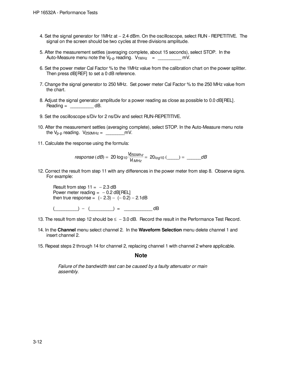
5.After the measurement settles (averaging complete, about 15 seconds), select STOP. In the
6.Set the power meter Cal Factor % to the 1MHz value from the calibration chart on the power splitter. Then press dB[REF] to set a 0 dB reference.
7.Change the signal generator to 250 MHz. Set power meter Cal Factor % to the 250 MHz value from the chart.
8.Adjust the signal generator amplitude for a power reading as close as possible to 0.0 dB[REL]. Reading = __________ dB.
9.Set the oscilloscope s/Div for 2 ns/Div and select
10.After the measurement settles (averaging complete), select STOP. In the
11.Calculate the response using the formula:
response (dB) = 20 log10V250Mhz = 20log10 (_____) = ______dB
V1MHz
12.Correct the result from step 11 with any differences in the power meter from step 8. Observe signs. For example:
Result from step 11 = − 2.3 dB Power meter reading = − 0.2 dB[REL]
then true response = (− 2.3) − (− 0.2) − 2.1dB
(__________) − (__________) = ____________ dB
13.The result from step 12 should be ≤ − 3.0 dB. Record the result in the Performance Test Record.
14.In the Channel menu select channel 2. In the Waveform Selection menu delete channel 1 and insert channel 2.
15.Repeat steps 2 through 14 for channel 2, replacing channel 1 with channel 2 where applicable.
Note
Failure of the bandwidth test can be caused by a faulty attenuator or main assembly.
