HP 16532A - Performance Tests
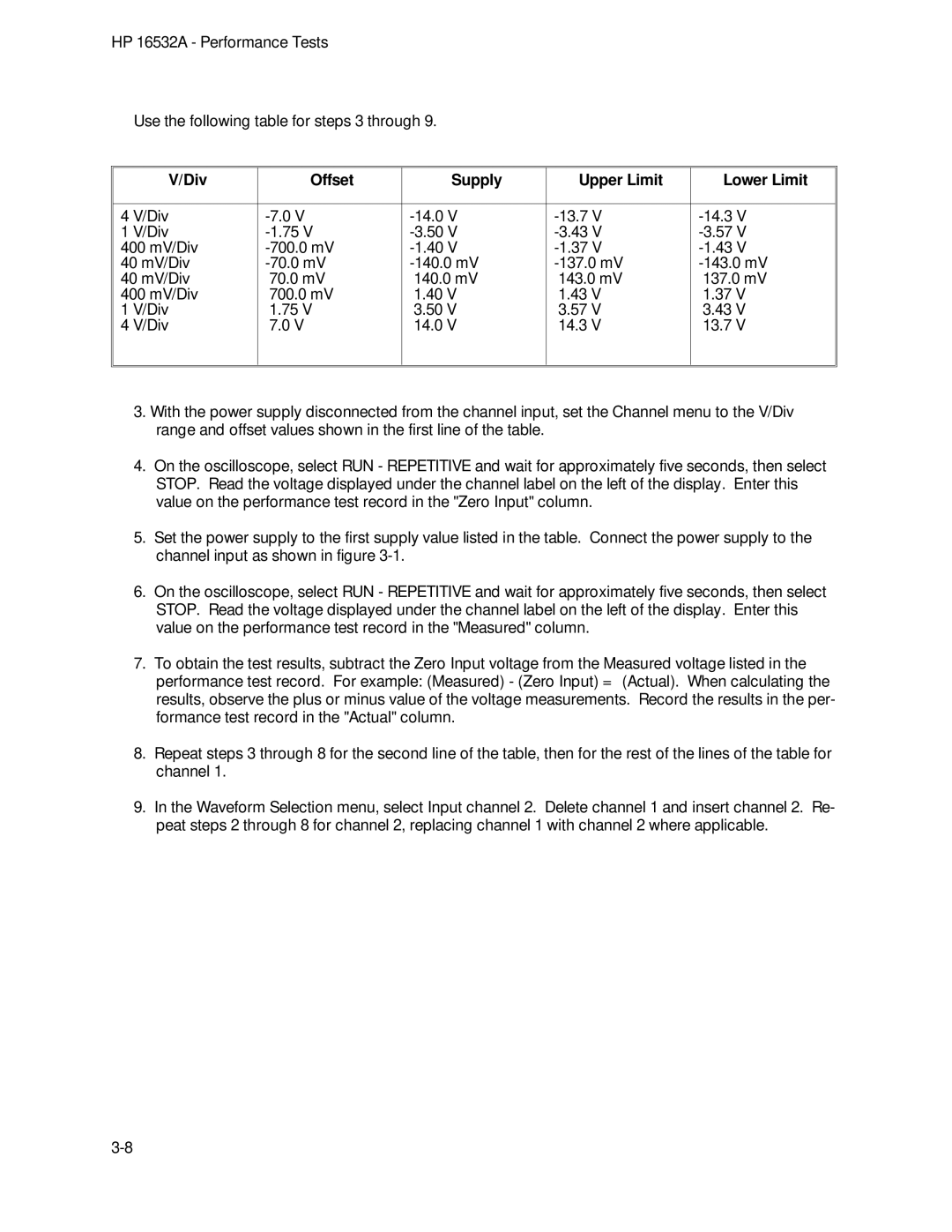
Use the following table for steps 3 through 9.
V/Div | Offset | Supply | Upper Limit | Lower Limit |
|
|
|
|
|
4 V/Div | ||||
1 V/Div | ||||
400 mV/Div | ||||
40 mV/Div | ||||
40 mV/Div | 70.0 mV | 140.0 mV | 143.0 mV | 137.0 mV |
400 mV/Div | 700.0 mV | 1.40 V | 1.43 V | 1.37 V |
1 V/Div | 1.75 V | 3.50 V | 3.57 V | 3.43 V |
4 V/Div | 7.0 V | 14.0 V | 14.3 V | 13.7 V |
|
|
|
|
|
|
|
|
|
|
3.With the power supply disconnected from the channel input, set the Channel menu to the V/Div range and offset values shown in the first line of the table.
4.On the oscilloscope, select RUN - REPETITIVE and wait for approximately five seconds, then select STOP. Read the voltage displayed under the channel label on the left of the display. Enter this value on the performance test record in the "Zero Input" column.
5.Set the power supply to the first supply value listed in the table. Connect the power supply to the channel input as shown in figure
6.On the oscilloscope, select RUN - REPETITIVE and wait for approximately five seconds, then select STOP. Read the voltage displayed under the channel label on the left of the display. Enter this value on the performance test record in the "Measured" column.
7.To obtain the test results, subtract the Zero Input voltage from the Measured voltage listed in the performance test record. For example: (Measured) - (Zero Input) = (Actual). When calculating the results, observe the plus or minus value of the voltage measurements. Record the results in the per- formance test record in the "Actual" column.
8.Repeat steps 3 through 8 for the second line of the table, then for the rest of the lines of the table for channel 1.
9.In the Waveform Selection menu, select Input channel 2. Delete channel 1 and insert channel 2. Re- peat steps 2 through 8 for channel 2, replacing channel 1 with channel 2 where applicable.