HP 16532A - Service
Verifying the System Clock
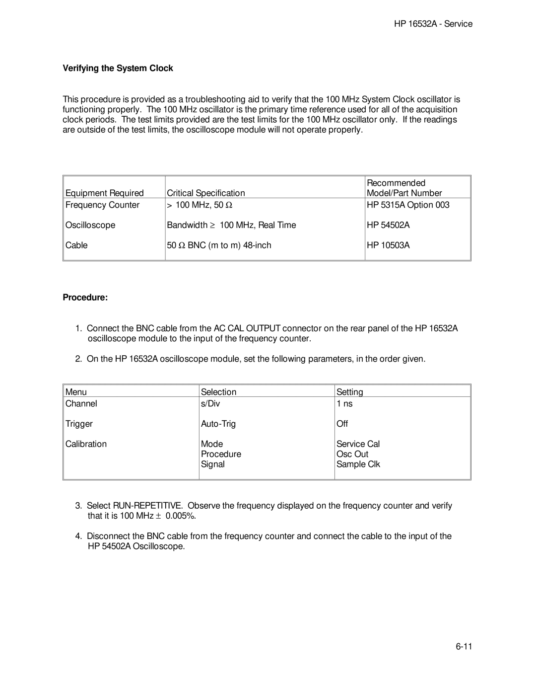
This procedure is provided as a troubleshooting aid to verify that the 100 MHz System Clock oscillator is functioning properly. The 100 MHz oscillator is the primary time reference used for all of the acquisition clock periods. The test limits provided are the test limits for the 100 MHz oscillator only. If the readings are outside of the test limits, the oscilloscope module will not operate properly.
|
| Recommended |
Equipment Required | Critical Specification | Model/Part Number |
Frequency Counter | > 100 MHz, 50 W | HP 5315A Option 003 |
Oscilloscope | Bandwidth ³ 100 MHz, Real Time | HP 54502A |
Cable | 50 W BNC (m to m) | HP 10503A |
|
|
|
|
|
|
Procedure:
1.Connect the BNC cable from the AC CAL OUTPUT connector on the rear panel of the HP 16532A oscilloscope module to the input of the frequency counter.
2.On the HP 16532A oscilloscope module, set the following parameters, in the order given.
Menu | Selection | Setting |
Channel | s/Div | 1 ns |
Trigger | Off | |
Calibration | Mode | Service Cal |
| Procedure | Osc Out |
| Signal | Sample Clk |
|
|
|
|
|
|
3.Select
4.Disconnect the BNC cable from the frequency counter and connect the cable to the input of the HP 54502A Oscilloscope.