HP 16532A - Service
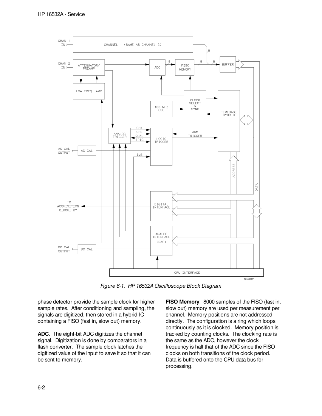
Figure 6-1. HP 16532A Oscilloscope Block Diagram
phase detector provide the sample clock for higher sample rates. After conditioning and sampling, the signals are digitized, then stored in a hybrid IC containing a FISO (fast in, slow out) memory.
ADC. The
FISO Memory. 8000 samples of the FISO (fast in, slow out) memory are used per measurement per channel. Memory positions are not addressed directly. The configuration is a ring which loops continuously as it is clocked. Memory position is tracked by counting clocks. The clocking rate is the same as the ADC, however the clock frequency is half that of the ADC since the FISO clocks on both transitions of the clock period. Data is buffered onto the CPU data bus for processing.