Appearance
U200-A
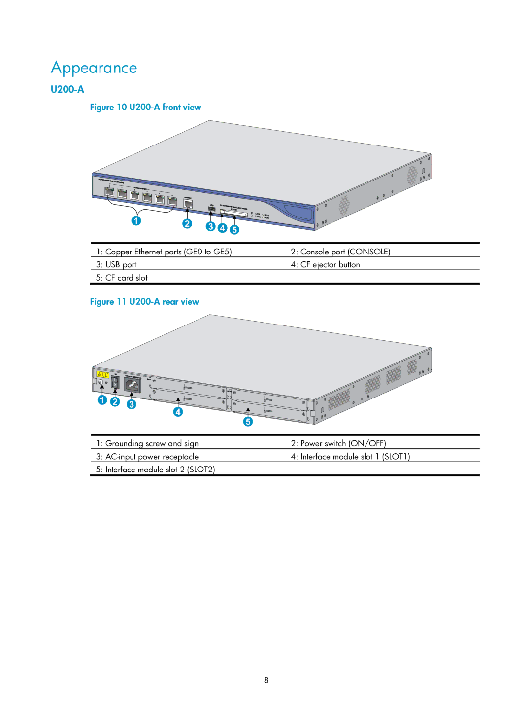
Figure 10 U200-A front view
1: Copper Ethernet ports (GE0 to GE5) | 2: Console port (CONSOLE) |
3: USB port | 4: CF ejector button |
5: CF card slot |
|
Figure 11 U200-A rear view
1: Grounding screw and sign | 2: Power switch (ON/OFF) |
3: | 4: Interface module slot 1 (SLOT1) |
5: Interface module slot 2 (SLOT2) |
|
8
