Table C-1. Network Interface Configuration Options 2
Ansi Performance Report Messages Disable Enable Disable
Network Initiated LLB Enable Enable Disable
Network Initiated PLB Enable Enable Disable
DTE Interface Configuration Options
Table C-2. DTE Interface Configuration Options 1
RBS RBS RBS RBS RBS RBS RBS RBS RBS
Table C-2. DTE Interface Configuration Options 2
Value Meaning
Sync Data Port Configuration Options
Table C-3. Sync Data Port Configuration Options 1
Port Type E530 Factory 1 V.35 Factory RS449
Port Base Rate Nx64 Nx64 Nx56
Table C-3. Sync Data Port Configuration Options 2
Embedded Data Link Disable Enable Disable
EDL Management Link Disable Enable Disable
Invert Transmit Clock Disable Enable Disable
Table C-3. Sync Data Port Configuration Options 3
Action on Network Yellow Alarm Halt None Halt
Table C-3. Sync Data Port Configuration Options 4
Far-End Performance Statistics Disable Disable Maintain
Table C-3. Sync Data Port Configuration Options 5
Cross Connect Configuration Options
DTE-to-Network Assignment Options
Table C-4. DTE-to-Network Assignment Options
DTE01 DTE02 DTE03 DTE04 DTE05 DTE06 DTE07 DTE08 DTE24
Sync Data Port Assignment Options
Table C-5. Sync Data Port Assignment Options 1
Table C-5. Sync Data Port Assignment Options 2
Table C-5. Sync Data Port Assignment Options 3
D01 D02 D03 D04 D05 D06 D07 D08 D24
General Configuration Options
Table C-6. General Configuration Options 1
Table C-6. General Configuration Options 2
External Clock Rate KHz 1544 2048 1544
Communication Port Configuration Options
User Interface Configuration Options
Table C-7. Communication Port Configuration Options 1
Table C-7. Communication Port Configuration Options 2
Table C-7. Communication Port Configuration Options 3
External Device Configuration Options
Table C-8. External Device Configuration Options 1
Table C-8. External Device Configuration Options 2
Connect Prefix Text Field
Connect Indication String Text Field
Escape Sequence Text Field
Escape Sequence Delay sec None None 0.2 0.4 0.6 0.8
Table C-8. External Device Configuration Options 3
Disconnect String Text Field
Table C-9. Telnet Sessions Configuration Options
Telnet Sessions Configuration Options
Telnet Session Disable Enable Disable
Ethernet 10BaseT Port Configuration Options
Table C-10. Ethernet Port Configuration Options
Alarm and Trap Configuration Options
Table C-11. Alarm and Trap Configuration Options 1
Ascii Alarm Messages Disable Disable Com Port
Alarm & Trap Dial-Out Disable Enable Disable
Table C-11. Alarm and Trap Configuration Options 2
Call Retry Disable Enable Disable
Dial Out Delay Time min 3 4 5 6 7 8 9
Alternate Dial-Out Directory None None 1 2 3 4
Management and Communication Configuration Options
Communication Protocol Configuration Options
Table C-12. Communication Protocol Configuration Options 1
Node IP Address Text Field
Table C-12. Communication Protocol Configuration Options 2
PPP Slip
General Snmp Management Configuration Options
Table C-13. General Snmp Management Configuration Options
Snmp NMS Security Configuration Options
Table C-14. Snmp NMS Security Configuration Options
Snmp Traps Configuration Options
Table C-15. Snmp Traps Configuration Options 1
Snmp Traps Disable Enable Disable
Number of Trap Managers 1 1 2 3 4 5
Table C-15. Snmp Traps Configuration Options 2
General Traps Both Disable Warm AuthFail Both
Enterprise Specific Traps Enable Enable Disable
Link Traps Both Disable Up Down Both
Table C-15. Snmp Traps Configuration Options 3
Link Trap Interfaces All Network DTE T1s Ports All
Network Interface Options
Configuration Worksheets
DTE Interface Options
Sync Data Port Options Port
Sync Data Port Options Port
Network Interface Network Channel Allocation
DTE Drop/Insert DSX-1 Interface DTE DSX-1 Channel Allocation
DTE Signaling Assign N1 Voice RBS or Data
Channel
Sync Data Port Options
Acami
Disable , DTR
General Options
User Interface Communication Port
User Interface External Device Options
Alarm and Trap Configuration Options
User Interface Telnet Sessions Options
User Interface Ethernet Port Options
Management and Communication Communication Protocol Options
Snmp NMS Security Options
Management and Communication
Snmp Traps Options
Pin Assignments
Table D-1. T1 Network Interface Connector Signal Pin Number
T1 Network Interface
Figure D-1. T1 Line Interface Cable, RJ48C-to-RJ48C
DTE Drop/Insert Interface
Figure D-3. DTE Drop/Insert DSX-1 Cable
10BaseT Connector
Use Pin #
Table D-3. COM Port Connector Signal Direction Pin Number
COM Port Interface
Figure D-4. COM Port-to-PC Cable
Pin
Serial Crossover Cable
Pin P2
EIA-530-A Port Interface Connector
EIA-530-A-to-RS-449 Adapter
Figure D-7. EIA-530-A-to-RS-449 Adapter
Pin Assignments
EIA-530-A-to-V.35 Adapter
Figure D-8. EIA-530-A-to-V.35 Adapter
Pin Assignments
EIA-530-A-to-X.21 Adapter
Direction Pin Number
Table D-8. External Clock Connector Signal Pin Number
External Clock Interface
MIB II RFC
Snmp MIB Objects
Group
System Group, MIB
System Group sysServices Object system
Interface Group, MIB
System Group sysName Object system
System Group sysLocation Object system
Interface Group ifIndex Object ifEntry
Interface Group ifDescr Object ifEntry
Interface Group ifAdminStatus Object ifEntry
Interface Group ifType Object ifEntry
Interface Group ifMtu Object ifEntry
Interface Group ifSpeed Object ifEntry
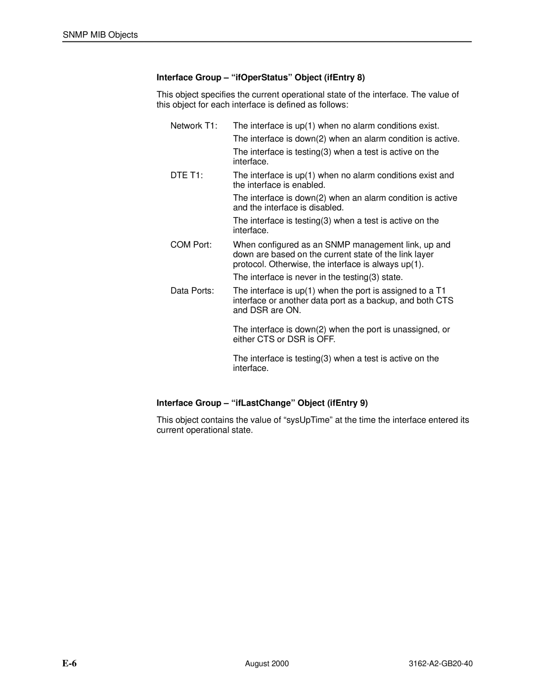
Interface Group ifOperStatus Object ifEntry
Interface Group ifLastChange Object ifEntry
IP Group, MIB
Interface Group Input Counters objects ifEntry 10 to ifEntry
IP Group ipForwarding Object ip
IP Group ipAddrTable Object ip
IP Group ipAdEntAddr Object ipAddrEntry
IP Group ipAdEntIfIndex Object ipAddrEntry
IP Group ipRouteDest Object ipRouteEntry
IP Group ipRouteIfIndex Object ipRouteEntry
TCP Group, MIB
Icmp Group, MIB
UDP Group, MIB
Transmission Group, MIB
DS1/E1 MIB RFC
Snmp Group, MIB
Near End Group dsx1TimeElapsed Object dsx1ConfigEntry
Near End Group dsx1ValidIntervals Object dsx1ConfigEntry
Near End Group dsx1LineType Object dsx1ConfigEntry
Near End Group dsx1LineCoding Object dsx1ConfigEntry
Near End Group dsx1CircuitIdentifier Object dsx1ConfigEntry
Near End Group dsx1SendCode Object dsx1ConfigEntry
Near End Group dsx1LoopbackConfig Object dsx1ConfigEntry
Near End Group dsx1LineStatus Object dsx1ConfigEntry
Near End Group dsx1SignalMode Object dsx1ConfigEntry
Near End Group dsx1Fdl Object dsx1ConfigEntry
DS1 Fractional Group, DS1/E1 MIB
Far End Group, DS1/E1 MIB
Near End Group The DS1 Total Table Objects dsx1TotalEntry
RS-232-like MIB RFC
General Port Table, RS-232-like MIB
Number of Ports rs232Number Object rs232
General Port Table rs232PortIndex Object rs232PortEntry
General Port Table rs232PortInSpeed Object rs232PortEntry
General Port Table rs232PortType Object rs232PortEntry
General Port Table rs232PortOutSpeed Object rs232PortEntry
Asynchronous Port Table, RS-232-like MIB
Input Signal Table, RS-232-like MIB
Input Signal Table rs232InSigName rs232InSigEntry
Input Signal Table rs232InSigState rs232InSigEntry
Input Signal Table rs232InSigChanges rs232InSigEntry
Output Signal Table, RS-232-like MIB
Output Signal Table rs232OutSigName rs232OutSigEntry
Output Signal Table rs232OutSigState rs232OutSigEntry
Output Signal Table rs232OutSigChanges rs232OutSigEntry
Generic Interface Test Table, Generic Interface MIB
3162-A2-GB20-40 August
Enterprise MIB
IP Network Addressing Scenario
Standalone at the Central Site
Network
Local Carrier with Remote Standalone
Figure F-2. Local Carrier with Remote Standalone
Local and Remote Carriers Different Subnets
Figure F-3. Local Carrier Connected to Remote Carriers
Local and Remote Carriers Same Subnet
Multiple NMSs
Figure F-5. Multiple COM Ports Connected to Different NMSs
Equipment Feature Number
Equipment List
Equipment List
Glossary
GL-1
GL-2
GL-3
GL-4
GL-5
GL-6
GL-7
GL-8
Index
Numbers
IN-2
Index
IN-3
IN-4
IN-5