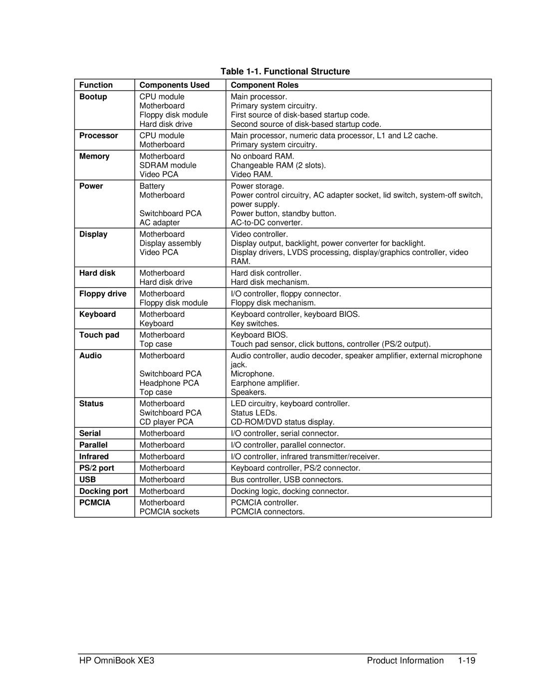
Table 1-1. Functional Structure
Function
Bootup
Processor
Memory
Power
Display
Hard disk
Floppy drive
Keyboard
Touch pad
Audio
Status
Serial
Parallel
Infrared
PS/2 port
USB
Docking port
PCMCIA
Components Used
CPU module Motherboard Floppy disk module Hard disk drive
CPU module
Motherboard
Motherboard SDRAM module Video PCA
Battery
Motherboard
Switchboard PCA AC adapter
Motherboard Display assembly Video PCA
Motherboard Hard disk drive
Motherboard Floppy disk module
Motherboard
Keyboard
Motherboard
Top case
Motherboard
Switchboard PCA Headphone PCA Top case
Motherboard Switchboard PCA CD player PCA
Motherboard
Motherboard
Motherboard
Motherboard
Motherboard
Motherboard
Motherboard PCMCIA sockets
Component Roles
Main processor.
Primary system circuitry.
First source of
Second source of
Main processor, numeric data processor, L1 and L2 cache. Primary system circuitry.
No onboard RAM.
Changeable RAM (2 slots).
Video RAM.
Power storage.
Power control circuitry, AC adapter socket, lid switch,
Power button, standby button.
Video controller.
Display output, backlight, power converter for backlight.
Display drivers, LVDS processing, display/graphics controller, video RAM.
Hard disk controller.
Hard disk mechanism.
I/O controller, floppy connector.
Floppy disk mechanism.
Keyboard controller, keyboard BIOS.
Key switches.
Keyboard BIOS.
Touch pad sensor, click buttons, controller (PS/2 output).
Audio controller, audio decoder, speaker amplifier, external microphone jack.
Microphone. Earphone amplifier. Speakers.
LED circuitry, keyboard controller.
Status LEDs.
I/O controller, serial connector.
I/O controller, parallel connector.
I/O controller, infrared transmitter/receiver.
Keyboard controller, PS/2 connector.
Bus controller, USB connectors.
Docking logic, docking connector.
PCMCIA controller.
PCMCIA connectors.
HP OmniBook XE3 | Product Information |