Disassembly Flowchart
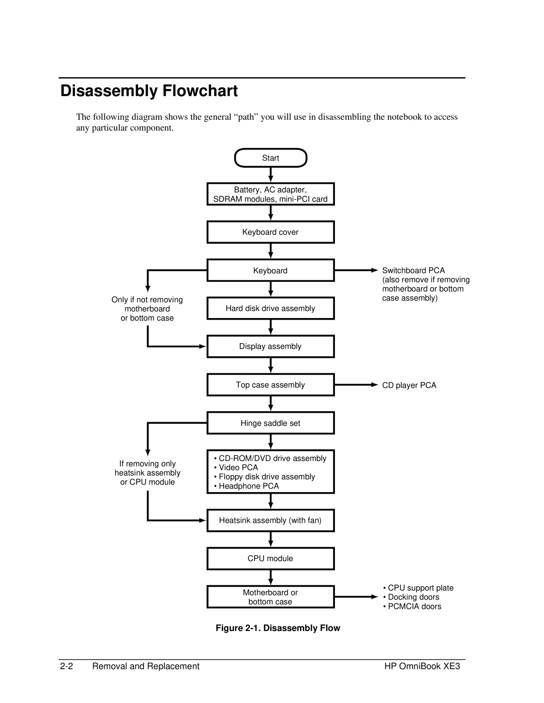
The following diagram shows the general “path” you will use in disassembling the notebook to access any particular component.
Only if not removing
motherboard
or bottom case
If removing only
heatsink assembly
or CPU module
Start
Battery, AC adapter,
SDRAM modules,
Keyboard cover
Keyboard
Hard disk drive assembly
Display assembly
Top case assembly
Hinge saddle set
•
•Video PCA
•Floppy disk drive assembly
•Headphone PCA
Heatsink assembly (with fan)
CPU module
Motherboard or
bottom case
![]() Switchboard PCA (also remove if removing motherboard or bottom case assembly)
Switchboard PCA (also remove if removing motherboard or bottom case assembly)
![]() CD player PCA
CD player PCA
•CPU support plate ![]() • Docking doors
• Docking doors
•PCMCIA doors
Figure 2-1. Disassembly Flow
Removal and Replacement | HP OmniBook XE3 |