SuperStack
3Com Corporation 5400 Bayfront Plaza Santa Clara, California
Contents
Setting UP for Management
Technical Specifications and PIN-OUTS
3Com Knowledgebase Web Services
About this Guide
Icon Description
Conventions
Convention Description
Registration
Related Documentation
Product
Documentation
About this Guide
Balancer
Server Load Balancer
Feature Server Load Balancer Plus Memory
Feature Server Load Balancer Plus Algorithms
12 10/100 LAN Ports
Server Load
Balancer Front View Detail
10/100BASE-T Port Status LEDs
Color Indicates Power/Self Test LED
Power LED
1000BASE-SX Port Status LEDs
Power Socket
Balancer Rear View Detail
Documentation shipped with the power system
Advanced Redundant Power System output
Type 3 Power Module, read the Safety Information section
Disconnecting the power cord
Installing the Server Load
Installing the Server Load Balancer
Rack-mounting
Server Load Balancer if they have been fitted
Placing Units On
Choosing
Correct Cables
Top of Each Other
Powered-up and ready for operation
Power-up
Sequence
Problem Suggested Solution
On powering-up, the Power/Self Test LED lights yellow
Setting UP for Management
Assigning an IP
Methods Managing Server Load Balancer
Address
SEC
Setting UP for Management
Interface
Security Warning Window
To install the plug-in, complete the following steps
Web Interface pages appears
Interfacesteps
Network Password window appears
After a management session
Banner
Using the Web Interface
Web interface is made up of three areas
Navigation Tree
System Summary
Summary information is displayed in a two tables
Device Summary
Port Hotspots
Unit Hotspot
Control Buttons
Color Action
Logical View
Button Action
Help View
Management
Setting up Snmp
Trap Community String field is defaulted to public
Specifying
Operating Software
Upgrading
Load Balancer
Working with the WEB Interface
Server Load Balancing
Example
Configuration
Balancing
Approximately double the performance of Server B
Configuring for Non-redundant Server Load Balancing
Click Next. The Getting Started Password page appears
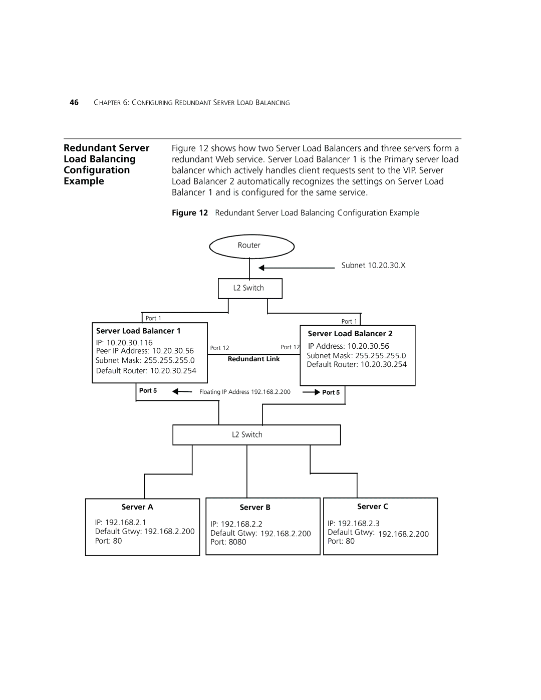
Configuring Redundant
Redundant Server
Balancer 1 and is configured for the same service
Load Balancing
Redundancy
Configuring for
Active-Passive
Load Balancer for active-passive redundancy
Enter 10.20.30.56 in the Device B IP Address field
Active-Active
Load Balancer for active-active redundancy
Click Next. The Getting Started IP Settings page appears
Enter 25 in the Virtual router ID a field
Setting
Settings
Enter 26 in the Virtual router ID B field
Configuring Redundant Server Load Balancing
Redirection
Cache Redirection Configuration Example
Subnet
Configuration
Defining a Cache
Non-redundant
Click Next Click Finish. Your cache subnet has been added
Assigning Caches to
Services
Adding a Cache
Been created
Steps
Enter a descriptive name, such as Cache2, in the Name field
Supported Algorithms Description Destination
Weighted Round Robin
Weighted Least
Round Robin
Retries field
Timeout
This sets the number of retries a health check is attempted
Balancing
Click Next. The Server Subnet Define Subnet page appears
Click Finish. Your server subnet has been added
Changing Lan Port Roles
Adding a Server
Enter a descriptive name, such as Web, in the Name field
Click Continue with Advanced Settings
Highlight Http and click the Next
Assigning Servers
To Service
Server load balancing service
Showing Status
Click on the cell next to Server A. a pop-up menu appears
Click Server Assignments
Enter 8080 in the Server port field Click OK
This user group
Adding a User
Group
To add a user group, complete the following steps
To assign permissions, complete the following steps
Click Permissions
Quickest Average
Supported Algorithms Description Round Robin
Quickest Last Response
Response
This sets the number of retries in a health check period
Filters
Select the attack filters you wish to enable and click OK
Mitigation
Filter Description
Modifying Monitor Access
Modifying Admin Access
Select Security User
Configuring for Load Balancing
Safety Information
Important Safety
Information
Important Safety Information
Personnel qualifié
’information de
Sécurité Importante
Hub plus étroites
’information de Sécurité Importante
Wichtige Sicherheitsinformat ionen
Europe
Achtung Faseroptikanschlüsse Optische Sicherheit
Appendix a Safety Information
PIN -OUTS
Specifications
Balancer and the Server Load Balancer Plus
Pin to RS232 25-pin
Console Port Cable
PC-AT Serial
Pin to 9-pin
Online Technical
Services
3Com
Username anonymous
Asia, Pacific Rim
Europe, Middle East Africa
North America
Country Telephone Number Fax Number
Appendix C Technical Support
Index
Numbers
Specifications, system 83 summary view
Summary view 32 World Wide Web WWW
Index
Superstack 3 Server Load Balancer 3C16120
Obtaining Warranty Service
Warranties Exclusive
Other Services
Regulatory Notices