Getting Started - RAID Array 410 for Windows NT – Intel
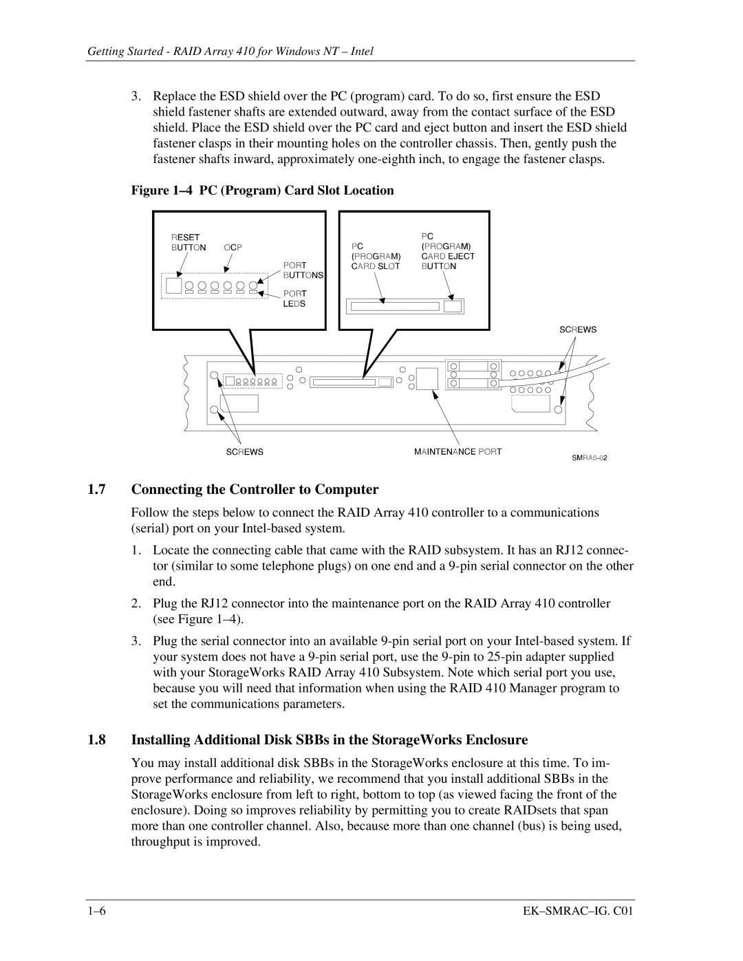
3.Replace the ESD shield over the PC (program) card. To do so, first ensure the ESD shield fastener shafts are extended outward, away from the contact surface of the ESD shield. Place the ESD shield over the PC card and eject button and insert the ESD shield fastener clasps in their mounting holes on the controller chassis. Then, gently push the fastener shafts inward, approximately
Figure 1–4 PC (Program) Card Slot Location
1.7Connecting the Controller to Computer
Follow the steps below to connect the RAID Array 410 controller to a communications (serial) port on your
1.Locate the connecting cable that came with the RAID subsystem. It has an RJ12 connec- tor (similar to some telephone plugs) on one end and a
2.Plug the RJ12 connector into the maintenance port on the RAID Array 410 controller (see Figure
3.Plug the serial connector into an available
1.8Installing Additional Disk SBBs in the StorageWorks Enclosure
You may install additional disk SBBs in the StorageWorks enclosure at this time. To im- prove performance and reliability, we recommend that you install additional SBBs in the StorageWorks enclosure from left to right, bottom to top (as viewed facing the front of the enclosure). Doing so improves reliability by permitting you to create RAIDsets that span more than one controller channel. Also, because more than one channel (bus) is being used, throughput is improved.
|