Chapter 1. Unpacking and Setting Up Your RAID Array 410 Subsystem Components
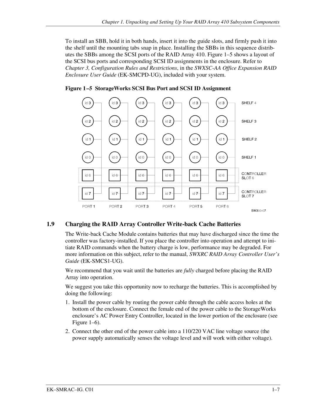
To install an SBB, hold it in both hands, insert it into the guide slots, and firmly push it into the shelf until the mounting tabs snap in place. Installing the SBBs in this sequence distrib- utes the SBBs among the SCSI ports of the RAID Array 410. Figure
Figure 1 –5 StorageWorks SCSI Bus Port and SCSI ID Assignment
1.9Charging the RAID Array Controller
The
We recommend that you wait until the batteries are fully charged before placing the RAID Array into operation.
We suggest you take this opportunity now to recharge the batteries. This is accomplished by doing the following:
1.Install the power cable by routing the power cable through the cable access holes at the bottom of the enclosure. Connect the female end of the power cable to the StorageWorks enclosure’s AC Power Entry Controller, located in the lower portion of the enclosure (see Figure
2.Connect the other end of the power cable into a 110/220 VAC line voltage source (the power supply automatically senses the voltage level and will work with either voltage).
|