| 8 |
This chapter describes several factors to be considered with a 41210 Bridge
8.1Interrupts
PCI Express provides interrupt messages that emulate the legacy wired mechanism. This allows IO devices to signal
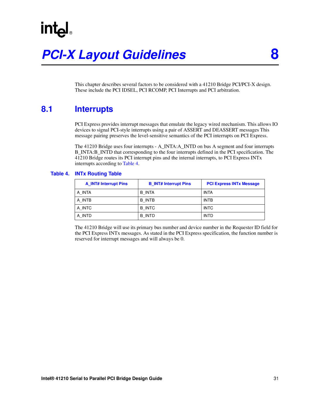
The 41210 Bridge uses four interrupts - A_INTA:A_INTD on bus A segment and four interrupts B_INTA:B_INTD that corresponding to the four interrupts defined in the PCI specification. The 41210 Bridge routes its PCI interrupt pins and the internal interrupts, to PCI Express INTx interrupts according to Table 4.
Table 4. INTx Routing Table
A_INT# Interrupt Pins | B_INT# Interrupt Pins | PCI Express INTx Message |
|
|
|
A_INTA | B_INTA | INTA |
|
|
|
A_INTB | B_INTB | INTB |
|
|
|
A_INTC | B_INTC | INTC |
|
|
|
A_INTD | B_INTD | INTD |
|
|
|
The 41210 Bridge will use its primary bus number and device number in the Requester ID field for the PCI Express INTx messages. As stated in the PCI Express specification, the function number is reserved for interrupt messages and will always be 0.
Intel® 41210 Serial to Parallel PCI Bridge Design Guide | 31 |