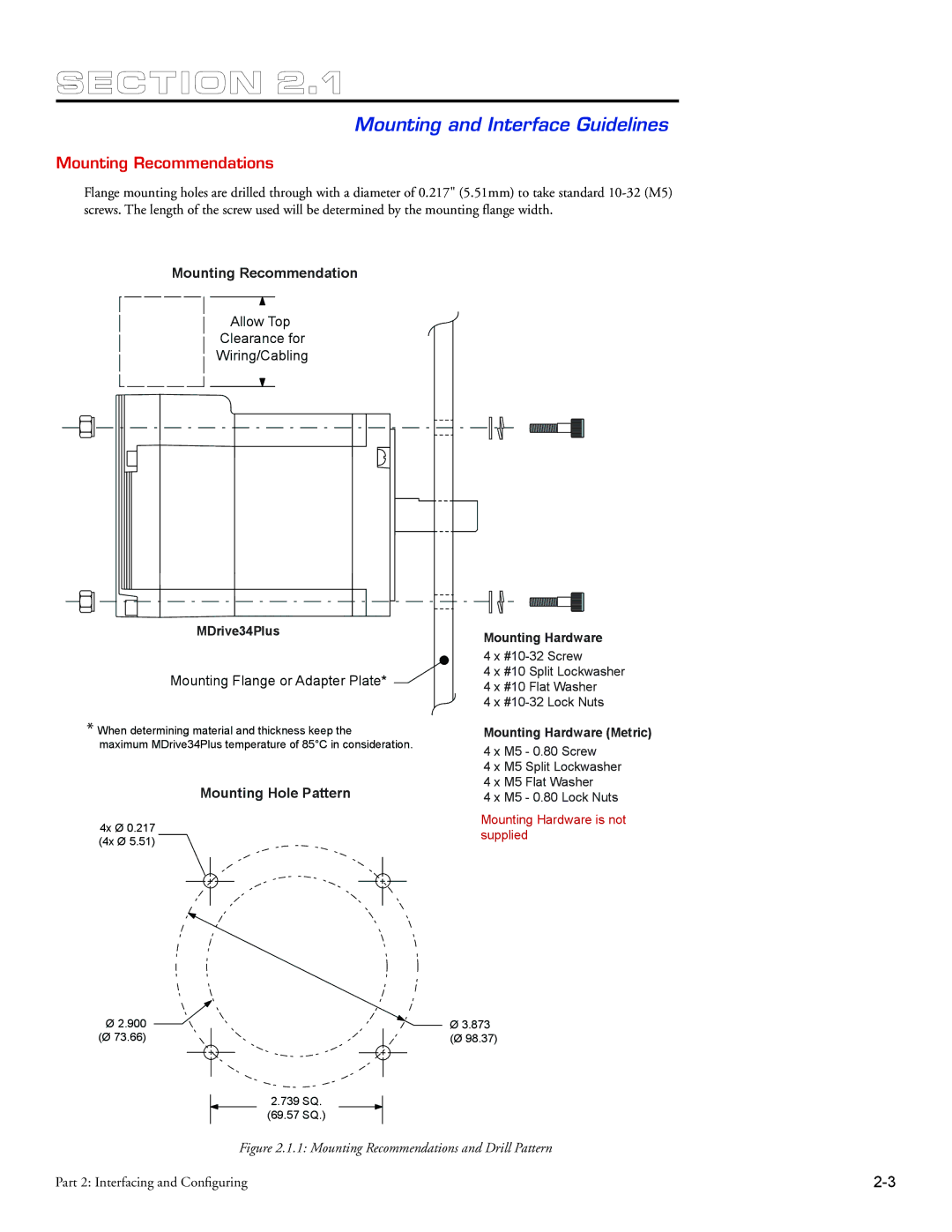
MDrive34Plus specifications
The Intelligent Motion Systems MDrive34Plus is an advanced integrated stepper motor and drive solution designed for a wide range of industrial automation applications. This compact device combines the motor, drive, and control into a single unit, simplifying installation and minimizing space requirements. This makes it an ideal choice for applications where space and efficiency are critical.One of the standout features of the MDrive34Plus is its high torque output, which enables it to handle significant loads with ease. Rated for a variety of torque configurations, this stepper motor provides the necessary power for demanding tasks while maintaining precise control and smooth operation. The MDrive34Plus also features a high-resolution microstepping capability, which enhances performance by providing smoother motion and reducing audible noise.
The device employs advanced digital control technologies, ensuring accurate positioning and minimizing erratic performance. Integrated with onboard intelligence, the MDrive34Plus allows for programmable settings, including acceleration, deceleration, and speed control, which can be customized according to the specific requirements of the application.
In terms of connectivity, the MDrive34Plus offers a range of communication protocols including RS-232, RS-485, and USB options, allowing it to easily integrate with various control systems and enable real-time monitoring and diagnostics. This flexibility is vital for modern automation solutions where adaptability is key.
The MDrive34Plus is also designed for robust performance in challenging environments, featuring an IP65 rated enclosure that protects against dust and moisture. This makes it suitable for use in a variety of industrial settings such as packaging, assembly, and robotics.
Furthermore, the MDrive34Plus supports both open-loop and closed-loop control configurations. This versatility provides users with the ability to choose the best operational mode for their application, optimizing performance and efficiency.
In conclusion, the Intelligent Motion Systems MDrive34Plus is a powerful, flexible, and easy-to-install integrated motor and drive solution. With its high torque capabilities, advanced digital control features, diverse connectivity options, and robust design, it stands out as an excellent choice for modern automation challenges. Whether for precise positioning tasks or heavy load handling, the MDrive34Plus is equipped to meet a broad spectrum of operational demands.

