4 MENU SWITCH SETTING
Besides the physical switches on the unit, a selection of MENU switches are provided. These can be displayed on the counter display or a connected monitor. Data set in the MENU switches are stored in the VCRÕs
●Storing and calling up the current menu switch setting
●Restoring the menu switches to the factory setting
●Calling up the Direct Access group of menu switches which are clustered by function (Direct Access facility)
●Erasing all registered contents on the User Page (User Page facility)
●Menu lock function
4 MENU SWITCH SETTING
4-1 MENU DISPLAY MODES
● 00E OPTIMUM REC CURRENT function (record- |
ing current automatic adjustment function) |
To automatically adjust the recording current, select |
this menu function and press the [HOLD] and [REC] |
buttons simultaneously. |
For details, refer to ÒRecording current adjustmentÓ |
on page 38. |
● 00F FIXED TIME ENTRY |
|
|
|
| ||
|
| [Counter display] |
| ||
| Usual display |
| Usual display |
| |
|
| H | M | S | F |
| CTL 1:23:45:20 |
|
|
|
|
| [MENU] button |
|
|
| |
|
| MENU |
|
|
|
| Top menu display |
|
|
|
|
| D95:525/625 |
|
|
|
|
| SET+HOLD[POWER OFF>525 |
|
|
|
|
| 00A:MENU SETTING |
|
|
|
|
| SET+HOLD INITIAL | H | M | S | F |
|
|
|
|
| |
| 00B:DIRECT ACCESS | Jog dial |
|
|
|
| SET+HOLD>ON |
|
|
| |
MENU |
|
|
|
| |
00C:USER PAGE |
|
|
|
| |
|
|
|
|
| |
| SET+HOLD>INITIAL |
|
|
|
|
| 00D:MENU LOCK |
|
|
|
|
| SET+HOLD>OFF |
|
|
|
|
|
| Jog dial |
|
|
|
| Menu switch setting display |
|
|
| |
| 002:OPERATION LOCK |
|
|
|
|
| OFF |
|
|
|
|
| 003:SYNC SELECT |
|
|
|
|
| AUTO | H | M | S | F |
|
|
|
|
| |
| 005:AUTO TRACKING |
|
|
|
|
MENU | ON | Jog dial |
|
|
|
| 008:CAP LOCK(525) |
|
|
| |
| SW SEL |
|
|
|
|
| 009:CAP |
|
|
|
|
| ACCELERATION |
|
|
|
|
| Hour meter data display | Jog dial |
|
|
|
|
|
|
|
| |
| DH:DRUM HOUR METER |
|
|
|
|
| 0600H |
|
|
|
|
|
| H | M | S | F |
MENU |
|
|
|
|
|
| User page display | Jog dial |
|
|
|
|
|
|
|
| |
| U01 :(FOR USER) |
|
|
|
|
| U02 :(FOR USER) |
|
|
|
|
|
| H | M | S | F |
| U03 :(FOR USER) |
|
|
|
|
MENU | U04 :(FOR USER) |
|
|
|
|
|
|
|
|
| |
| U05 :(FOR USER) |
|
|
|
|
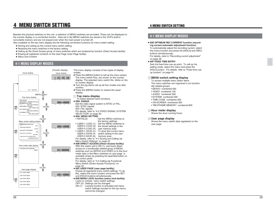
The menu display consists of four types of display modes. ● Press the [MENU] button to call up the menu screen. The menu switch Nos. are shown on the counter display. The selected menu switch No. blinks on the
Top menu display
To select desired menu functions.
●D95: 525/625
Set the video signal system to NTSC or PAL.
525:NTSC signals
625:PAL signals
For details, refer to
●00A: MENU SETTING
¥ | INITIAL(0) | : Set the MENU switches to |
|
| the factory settings. |
¥
¥ | LOAD (5) | user memory area. | |
SAVE (2) | : To store the current menu | ||
|
| SAVE (4) | switch setting in the user |
| memory area. | ||
For details, refer to | |||
Menu Switch SettingsÓ on page 32. | |||
●00B DIRECT ACCESS (Direct Access facility) With this switch set to ON (1),
For details, refer to
●00C USER PAGE (user page facility)
Erases all registered menu switch settings. To do this, select this menu function and press the SET and [HOLD] buttons simultaneously.
●00D MENU LOCK function (menu lock facility) Locks or unlocks menu switch settings.
OFF (0) : Settings can be changed.
ON (1) : Locking function is activated and menu
switch settings (except for the top menu) cannot be changed.
Sets the fixed time cue up point. To call up the |
setting mode, select this menu and press the |
[HOLD] button. For details, refer to ÒFixed time cue |
2up functionÓ on page 91. |
| MENU switch setting display |
| To access multiple menu switch items |
| The menu switches are organized in six function- |
| ally related groups. |
| ¥ SERVO numbered 000 |
| ¥ VIDEO numbered 100 |
| ¥ AUDIO numbered 200 |
| ¥ SYSTEM numbered 300 |
| ¥ TIME CODE numbered 400 |
| ¥ |
3 | ¥ TBC/FRAME MEMORY numbered 600 |
| Hour meter display |
4Shows the drum running hours. | |
| User page display |
| Shows the menu switch data registered on the |
| user page. |
28 | 29 |