5 MENU SWITCH SETTING DETAILS
5-2 MENU SWITCH SETTING CONTENT
5 MENU SWITCH SETTING DETAILS |
|
[ | ] : Factory setting |
|
|
| Item |
| Setting |
Menu SW | Counter | ||
No. | display | display | display |
Content |
[ | ] : Factory setting |
|
|
|
| Item |
| Setting |
|
Menu SW | Counter | Content | ||
| ||||
No. | display | display | display |
|
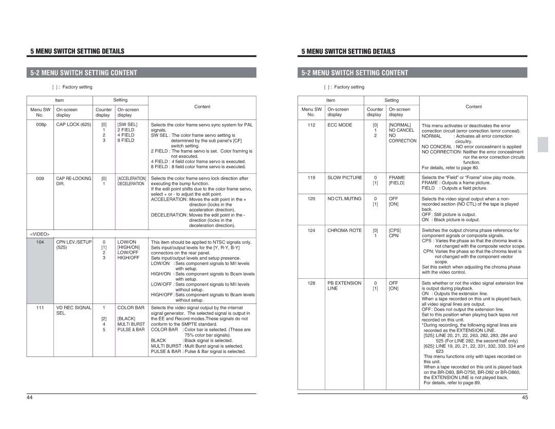
008p | CAP LOCK (625) | [0] | [SW SEL] |
|
| 1 | 2 FIELD |
|
| 2 | 4 FIELD |
|
| 3 | 8 FIELD |
Selects the color frame servo sync system for PAL | |
signals. | |
SW SEL : The color frame servo setting is | |
| determined by the sub panel’s [CF] |
| switch setting. |
2 | FIELD : The frame servo is set. Color framing is |
| not executed. |
4 | FIELD : 4 field color frame servo is executed. |
8 | FIELD : 8 field color frame servo is executed. |
112 | ECC MODE | [0] |
|
| 1 |
|
| 2 |
[NORMAL] NO CANCEL NO CORRECTION
This menu activates or deactivates the error | |
correction circuit (error correction /error conceal). | |
NORMAL | : Activates all error correction |
| circuitry. |
NO CONCEAL : NO error concealment is applied | |
NO CORRECTION: Neither the error concealment | |
| nor the error correction circuits |
| function. |
For details, refer to page 80. | |
009
CAP
[0] 1
[ACCELERATION] DECELERATION
Selects the color frame servo lock direction after executing the bump function. If the edit point shifts due to the color frame servo, select + or - to adjust the edit point. ACCELERATION : Moves the edit point in the + direction (locks in the acceleration direction). DECELERATION : Moves the edit point in the - direction (locks in the deceleration direction).
119 | SLOW PICTURE | 0 | FRAME | Selects the “Field” or “Frame” slow play mode. | |
|
| [1] | [FIELD] | FRAME : Outputs a frame picture. | |
|
|
|
| FIELD | : Outputs a field picture. |
120 | NO CTL MUTING | 0 | OFF | Selects the video signal output when a non- | |
|
| [1] | [ON] | recorded section (NO CTL) of the tape is played | |
|
|
|
| back. |
|
|
|
|
| OFF : Still picture is output. | |
|
|
|
| ON : Black picture is output. | |
|
|
|
| Switches the output chroma phase reference for | |
<VIDEO> |
|
|
|
104 | CPN LEV./SETUP | 0 | LOW/ON |
| (525) | [1] | [HIGH/ON] |
|
| 2 | LOW/OFF |
|
| 3 | HIGH/OFF |
111 | VD REC SIGNAL | 1 | COLOR BAR |
| SEL. |
|
|
|
| [2] | [BLACK] |
|
| 4 | MULTI BURST |
|
| 5 | PULSE & BAR |
This item should be applied to NTSC signals only. | ||
Sets input/output levels for the [Y, | ||
connectors on the rear panel. | ||
Sets input/output levels and setup presence. | ||
LOW/ON | : Sets component signals to MII levels | |
| with setup. | |
HIGH/ON | : Sets component signals to Bcam levels | |
| with setup. | |
LOW/OFF : Sets component signals to MII levels | ||
| without setup. | |
HIGH/OFF : Sets component signals to Bcam levels | ||
| without setup. | |
Selects the video signal output by the internal | ||
signal generator. The selected signal is output in | ||
the EE and Record modes.These signals do not | ||
conform to the SMPTE standard. | ||
COLOR BAR | : Color bar is selected. (These are | |
|
| 75% color bar signals). |
BLACK |
| : Black signal is selected. |
MULTI BURST : Multi Burst signal is selected. | ||
PULSE & BAR : Pulse & Bar signal is selected. | ||
124 | CHROMA ROTE | [0] | [CPS] | component signals or composite signals. |
|
| 1 | CPN | |
|
|
|
| CPS : Varies the phase so that the chroma level is |
|
|
|
| not changed with the composite vector scope. |
|
|
|
| CPN: Varies the phase so that the chroma level is |
|
|
|
| not changed with the component vector |
|
|
|
| scope. |
|
|
|
| Set this switch when adjusting the chroma phase |
|
|
|
| with the video control. |
128 | PB EXTENSION | 0 | OFF | Sets whether or not the video signal extension line |
| LINE | [1] | [ON] | is output during playback. |
|
|
|
| ON : Outputs the extension line. |
|
|
|
| When a tape recorded on this unit is played back, |
|
|
|
| all video signal lines are output. |
|
|
|
| OFF : Does not output the extension line. |
|
|
|
| Set to this position when playing back tapes not |
|
|
|
| recorded on this unit. |
|
|
|
| *During recording, the following signal lines are |
|
|
|
| recorded as the EXTENSION LINE. |
|
|
|
| [525]: LINE 20, 21, 22, 263, 282, 283, 284 and |
|
|
|
| 525 (For LINE 282, the second half only) |
|
|
|
| [625]: LINE 19, 20, 21, 22, 331, 332, 333, 334 and |
|
|
|
| 623 |
|
|
|
| This menu functions only with tapes recorded on |
|
|
|
| this unit. |
|
|
|
| When a tape recorded on this unit is played back |
|
|
|
| on the |
|
|
|
| the EXTENSION LINE is not played back. |
|
|
|
| For details, refer to page 89. |
44 | 45 |