13 |
|
|
| |||||
|
| |||||||
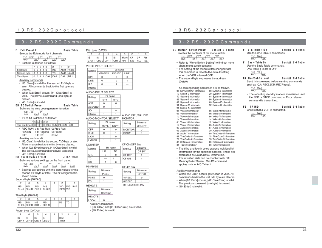
E9: Edit Preset 2 |
|
|
|
|
| Basic Table | ||
Selects the Edit mode for 4 channels. |
| |||||||
TxD | E9 |
| 3* |
| 3* |
| 3* |
|
RxD | 0A |
|
| 0A | 0A | 0A |
| |
• Each bit is defined as follows: |
|
| ||||||
| 7 | 6 | 5 | 4 | 3 | 2 | 1 | 0 |
First byte | 0 | 0 | 1 | 1 | 0 | INS | ASM | Video |
Second byte | 0 | 0 | 1 | 1 | 0 | TC | Aud2 | Aud1 |
Third byte | 0 | 0 | 1 | 1 | DA4 | DA3 | DA2 | DA1 |
Auxiliary commands |
|
|
|
| ||||
• | [56: Clear] is valid for the second TxD byte or |
| later. All commands back to the first byte are |
| cleared. |
Fifth byte (DATA3) |
|
|
|
|
| ||
7 | 6 | 5 | 4 | 3 | 2 | 1 | 0 |
IS | IS | IS | IS | MON | CF | CF | PB |
CH2 1 | CH2 0 | CH1 1 | CH1 0 | /IPT | SW | FLD | /EE |
VIDEO INPUT SELECT |
|
|
|
| |||
Setting |
|
| Bit name |
|
|
| |
VID GEN | DIG VID | LINE |
|
|
| ||
|
|
|
| ||||
CPN | 0 |
| 0 | 0 |
|
|
|
LINE | 0 |
| 0 | 1 |
|
|
|
SIF | 0 |
| 1 | — |
|
|
|
Internal | 1 |
| — | — |
|
|
|
13 |
|
| |||
|
| ||||
ED: Memory Switch Preset | |||||
Rewrites the contents of the menu switch. | |||||
TxD | ED | ** | ** | ** |
|
RxD |
| 0A | 0A | 0A | 0A |
•Refer to “Menu Switch Setting” to find out more about menu switch contents.
•The setting of the menu switch changed with this command is reset to the default setting when the VCR is turned OFF.
•The second byte expresses the address (Data0).
The corresponding addresses are as follows. | |
F6: JVC | ||
Use the JVC | ||
TxD | F6 |
|
RxD | 0A |
|
F7: Basic Table On | ||
Use the Basic Table commands. | ||
JVC |
| |
TxD | F7 |
|
RxD | 0A |
|
FA: Rec/DubRequest | ||
Send this command before sending commands | ||
such as [CA: REC], [CB: RECPause]. | ||
TxD | FA |
|
RxD | 0A |
|
• | When [02: Error] occurs, [41: ClearError] is |
| valid. The previous command (one byte) is |
| cleared. |
• | [40: Enter] is invalid. |
EB: TC Switch Preset |
|
| Basic Table | ||||||
Switches the time code generator function. | |||||||||
| TxD | EB |
|
| 3* |
|
|
|
|
| RxD |
| 0A |
| 0A |
|
| ||
• | Each bit is defined as follows: |
| |||||||
|
| 7 | 6 | 5 | 4 | 3 | 2 | 1 | 0 |
The first byte 0 | 0 | 1 | 1 | 0 | REC RUN REGEN | EXT | |||
• | REC RUN | : 1: Rec Run | 0: Free Run |
| |||||
| REGEN | : 1: Regene | 0: Preset |
| |||||
| EXT |
| : 1: Ext |
|
| 0: Int |
| ||
Auxiliary commands |
|
|
|
| |||||
•[56: Clear] is valid for the second TxD byte or later. All commands back to the first byte are cleared.
•When [02: Error] occurs, [41: ClearError] is valid. The previous command (one byte) is cleared.
•[40: Enter] is invalid.
EC: Panel Switch Preset |
|
|
| |
Switches various settings on the front panel. | ||||
TxD EC | ** | ** | ** | ** |
AUDIO INPUT SELECT | |||
Setting | Bit name | ||
IS**1 | IS**2 | ||
| |||
ANA | 0 | 0 | |
AES/EBU | 0 | 1 | |
SDI | 1 | — | |
Internal | 1 | 1 | |
AUDIO MONITOR SELECT | |||
Setting | Bit name | ||
MS**L | MS**R | ||
| |||
OFF | 0 | 0 | |
R CH | 0 | 1 | |
L CH | 1 | 0 | |
L+R CH | 1 | 1 | |
COUNTER |
|
| |
Setting | Bit name | ||
UB | TC | ||
| |||
CTL | 0 | 0 | |
TC | — | 1 | |
UB | 1 | 0 | |
AUDIO INPUT/AUDIO | ||
MONITOR |
|
|
Setting |
| Bit name |
| ||
| MON/IPT | |
|
| |
MONITOR |
| 0 |
INPUT |
| 1 |
CF ON/OFF SW | ||
Setting |
| Bit name |
|
| CF SW |
CF OFF | 0 | |
CF ON | 1 | |
10 | 20 | ||
40 | 88 | ||
89 | 90 | ||
87 | 09 | ||
91 | 92 | ||
94 |
|
| |
0a | :Video | 0b | :Video |
0c | :Video | 0d | |
1b | 0e | ||
1e | 1c | ||
0f | 1f | ||
1d | 05 | ||
06 | 07 | ||
03 | 30 | ||
31 | 80 | ||
81 | 79 | : | |
77 | 78 | ||
82 | 83 | ||
84 | :TBC | 86 | :TBC |
•The third and fourth bytes express individual bit information for the specified address. These are expressed as Data1/Data2 information.
•The rewritten data can be checked with D3: MemorySwitchSense. The D3 command applies only to JVC
•The recording standby mode is maintained until the REC or STOP command or Error release command is transmitted.
FB: VTR IND | ||
Checks that a VCR is connected. | ||
TxD | FB |
|
RxD |
| 0A |
| RxD | 0A | 0A | 0A | 0A |
| 0A |
• | Settings are defined with the input values for the | ||||||
| second TxD byte or later. The bit assignment is | ||||||
| shown below. |
|
|
|
|
| |
Second byte (DATA0) |
|
|
|
|
| ||
7 | 6 | 5 | 4 | 3 | 2 | 1 | 0 |
MS | MS | MS | MS |
| VID | DIG LINE | |
CH4 L CH4 R | CH3 L | CH3 R |
| GEN VID |
| ||
Third byte (DATA1) |
|
|
|
|
| ||
7 | 6 | 5 | 4 | 3 | 2 | 1 | 0 |
MS | MS | MS | MS |
| UB | TC |
|
CH2 L CH2 R CH1 L | CH1 R |
|
|
|
| ||
Fourth byte (DATA2) |
|
|
|
|
| ||
7 | 6 | 5 | 4 | 3 | 2 | 1 | 0 |
IS | IS | IS | IS |
| Rem |
|
|
CH4 1 CH4 0 | CH3 1 | CH3 0 |
| /9pin |
|
| |
PB PB/EE |
| CF 4/8 SW |
| |
|
|
| ||
Setting | Bit name | Setting | Bit name | |
PB/EE | CF FLD | |||
|
| |||
PB/EE | 0 | 4 FIELD | 0 | |
PB | 1 | 8 FIELD | 1 | |
REMOTE |
| 8 FIELD: (625) only | ||
|
|
| ||
Setting | Bit name |
|
| |
Rem/9pin |
|
| ||
|
|
| ||
REMOTE | 1 |
|
| |
LOCAL | 0 |
|
| |
Auxiliary commands |
|
| ||
•[56: Clear] and [41: ClearError] are invalid.
•[40: Enter] is invalid.
Auxiliary commands
•When [02: Error] occurs, [56: Clear] is valid. All commands back to the first TxD byte are cleared.
•When [02: Error] occurs, [41: ClearError] is valid. The previous command (one byte) is cleared.
•[40: Enter] is invalid.
132 | 133 |