3 CONNECTIONS |
|
|
|
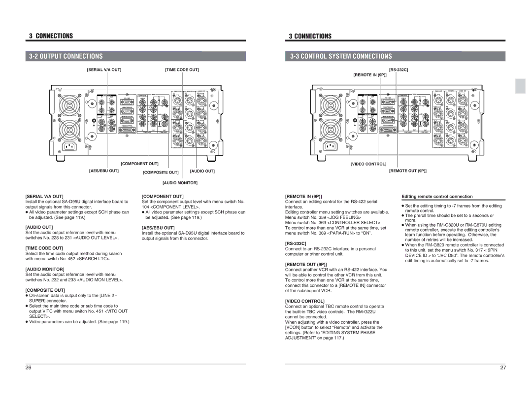
[SERIAL V/A OUT] | [TIME CODE OUT] |
3 CONNECTIONS
3-3 CONTROL SYSTEM CONNECTIONS
[RS-232C] [REMOTE IN (9P)]
|
|
|
|
| TIME CODE | AUDIO IN | AUDIO OUT |
|
|
|
| VIDEO | IN | CH1 | CH1 |
| SERIAL V / A |
| COMPOSITE |
|
|
| |
|
|
| REF |
|
| ||
IN | OUT | LINE IN |
|
|
| ||
| 1 |
| 75 |
|
| ||
|
|
|
|
| ON |
|
|
|
|
|
|
| OFF |
|
|
| 2 | REMOTE IN (9P) | Y | Y | OUT | CH2 | CH2 |
| AES / EBU |
| LINE1 |
|
| ||
IN | OUT | REMOTE OUT (9P) |
|
|
|
|
|
CH1/2 | CH1/2 |
|
|
|
|
|
|
|
|
|
|
| L | CH3 | CH3 |
|
|
| LINE2 |
|
| ||
CH3/4 | CH3/4 | VIDEO CONTROL |
|
| SUPER |
|
|
|
|
|
|
|
| ||
|
|
| IN | OUT | OUT |
|
|
|
|
| COMPONENT | COMPOSITE |
|
| |
|
|
|
|
| R | CH4 | CH4 |
| SERIAL V / A |
|
IN | OUT | |
| 1 | |
| 2 | REMOTE IN (9P) |
| AES / EBU |
|
IN | OUT | REMOTE OUT (9P) |
CH1/2 | CH1/2 |
|
CH3/4 | CH3/4 | VIDEO CONTROL |
|
| TIME CODE | AUDIO IN | AUDIO OUT |
| VIDEO | IN | CH1 | CH1 |
COMPOSITE |
|
|
| |
| REF |
|
| |
|
|
|
| |
LINE IN |
| 75 |
|
|
|
| ON |
|
|
|
| OFF |
|
|
Y | Y | OUT | CH2 | CH2 |
LINE1 |
|
| ||
|
| L | CH3 | CH3 |
LINE2 |
|
| ||
|
| SUPER |
|
|
IN | OUT | OUT |
|
|
COMPONENT | COMPOSITE |
|
| |
|
| R | CH4 | CH4 |
| AUDIO MONITOR |
|
| [COMPONENT OUT] |
|
[AES/EBU OUT] | [COMPOSITE OUT] | [AUDIO OUT] |
|
| |
| [AUDIO MONITOR] | |
AUDIO MONITOR
[VIDEO CONTROL]
[REMOTE OUT (9P)]
[SERIAL V/A OUT] Install the optional
●All video parameter settings except SCH phase can be adjusted. (See page 119.)
[AUDIO OUT] Set the audio output reference level with menu switches No. 228 to 231 <AUDIO OUT LEVEL>.
[TIME CODE OUT] Select the time code output method during search with menu switch No. 452 <SEARCH LTC>.
[AUDIO MONITOR] Set the audio output reference level with menu switches No. 232 and 233 <AUDIO MON LEVEL>.
[COMPOSITE OUT]
●
●Select the main time code or sub time code to output VITC with menu switch No. 451 <VITC OUT SELECT>.
●Video parameters can be adjusted. (See page 119.)
[COMPONENT OUT] Set the component output level with menu switch No. 104 <COMPONENT LEVEL>.
●All video parameter settings except SCH phase can be adjusted. (See page 119.)
[AES/EBU OUT] Install the optional
[REMOTE IN (9P)] Connect an editing control for the
[REMOTE OUT (9P)] Connect another VCR with an
[VIDEO CONTROL] Connect an optional TBC remote control to operate the
Editing remote control connection
●Set the editing timing to
●The preroll time should be set to 5 seconds or more.
●When using the
●When the
26 | 27 |