13 |
|
|
| ||
| |||||
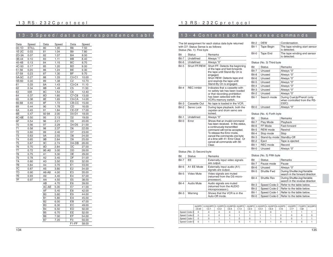
Data | Speed | Data | Speed | Data | Speed |
STILL | 80 | 1.00 | B8 | 7.50 | |
0.03 | 81 | 1.04 | B9 | 7.80 | |
0.07 | 82 | 1.07 | BA | 8.00 | |
0.10 | 83 | 1.11 | BB | 8.40 | |
0.13 | 84 | 1.15 | BC | 8.70 | |
0.17 | 85 | 1.20 | BD | 9.00 | |
0.20 | 86 | 1.24 | BE | 9.30 | |
0.23 | 87 | 1.30 | BF | 9.70 | |
0.27 | 88 | 1.33 | 10.00 | ||
0.30 | 89 | 1.38 | C2 | 10.70 | |
61 | 0.33 | 8A | 1.43 | 11.10 | |
62 | 0.34 | 8B | 1.49 | C5 | 11.50 |
63 | 035 | 8C | 1.54 | C6 | 12.40 |
64 | 0.37 | 8D | 1.60 | 13.00 | |
65 | 0.38 | 8E | 1.65 | 14.00 | |
0.40 | 8F | 1.72 | 15.00 | ||
69 | 0.44 | 90 | 1.78 | CD | 16.00 |
6A | 0.45 | 91 | 1.84 | 17.00 | |
6B | 0.47 | 2.00 | 18.00 | ||
0.50 | 95 | 2.13 | D2 | 19.00 | |
6F | 0.54 | 96 | 2.21 | D3 | 20.00 |
70 | 0.56 | 97 | 2.29 | 21.00 | |
71 | 0.58 | 98 | 2.37 | D6 | 22.00 |
72 | 0.60 | 99 | 2.46 | D7 | 23.00 |
73 | 0.63 | 9A | 2.55 | D8 | 24.00 |
74 | 0.65 | 9B | 2.64 | D9 | 25.00 |
75 | 0.67 | 9C | 2.74 | 26.00 | |
76 | 0.70 | 9D | 2.84 | DC | 27.00 |
77 | 0.72 | 3.00 | DD | 28.00 | |
78 | 0.75 | A1 | 3.30 | DE | 29.00 |
79 | 0.78 | A2 | 3.40 | DF | 31.00 |
7A | 0.80 | A3 | 3.50 | E0 | 32.00 |
7B | 0.84 | A4 | 3.70 | E1 | 33.00 |
7C | 0.87 | A5 | 3.80 | E2 | 34.00 |
7D | 0.90 | 4.00 | E3 | 35.00 | |
7E | 0.93 | A9 | 4.40 | E4 | 37.00 |
7F | 0.97 | AA | 4.50 | E5 | 38.00 |
|
| AB | 4.70 | E6 | 39.00 |
|
| 5.00 | E7 | 41.00 | |
|
| AF | 5.40 | E8 | 42.00 |
|
| B0 | 5.60 | E9 | 44.00 |
|
| B1 | 5.80 | EA | 45.00 |
|
| B2 | 6.00 | EB | 47.00 |
13 | ||
| ||
The bit assignment for each status data byte returned | ||
with D7: Status Sense is as follows: | ||
Status (No. 1): First byte | ||
Bit | Status | Remarks |
Undefined | Always “1” | |
Undefined | Always “0” | |
Short FF/REW | Short FF: Detects the beginning | |
|
| of the tape and |
|
| the tape until |
|
| engaged. |
|
| Short REW: Detects tape end |
|
| and rewinds the tape until |
|
| |
REC Inhibit | Indicates that a cassette with | |
|
| no safety tab has been loaded |
|
| or that recording prohibition |
|
| has been selected with the |
|
| VCR’s memory switch. |
Cassette Out | No tape is loaded in the VCR. | |
Servo Lock | During tape playback, both the | |
|
| capstan and drum servo are |
|
| locked. |
Undefined | Always “0” | |
Error | Shows that an invalid command | |
|
| has been received. In this status, |
|
| a continuously transmitted |
|
| command will not be accepted. |
|
| To release the Error mode, |
|
| cancel the commands one byte |
|
| at a time with 41: Error Clear. Or |
|
| cancel all commands with 56: |
|
| Clear. |
Status (No. 2) Second byte | ||
Bit | Status | Remarks |
EE | Externally input video signals | |
|
| are output. |
A1 EE Mode | Externally input audio (A1) | |
|
| signals are output. |
Video Mute | Video signals are muted | |
|
| (returned from the DS micro- |
|
| processor). |
Audio Mute | Audio signals are muted | |
|
| (returned from the AUDIO |
|
| microprocessor.). |
Warning | Shows that the VCR is in the | |
|
| |
DEW | Condensation. | |
Tape Begin | The tape winding start sensor | |
|
| is detected. |
Tape End | The tape winding end sensor | |
|
| is detected. |
Status (No. 3) Third byte | ||
Bit | Status | Remarks |
Unused | Always “0” | |
Unused | Always “0” | |
Unused | Always “0” | |
Unused | Always “0” | |
Unused | Always “0” | |
Unused | Always “0” | |
Unused | Always “0” | |
Search mode | During CueUp/Preroll (only | |
|
| when controlled from the RS- |
|
| 232C) |
Unused | Always “0” | |
Status (No. 4) Forth byte | ||
Bit | Status | Remarks |
Play Mode | Playback | |
FF Mode | ||
REW mode | Rewind | |
Stop mode | Stop | |
Eject | Tape is ejected | |
REC mode | Record | |
Unused | Always “0” | |
Status (No. 5) Fifth byte |
| |
Bit | Status | Remarks |
Pause mode | Pause | |
Unused | Always “0” | |
Shuttle Fwd | During Shuttle/Jog/Variable | |
|
| search in the forward direction |
Shuttle Rev | During Shuttle/Jog/Variable | |
|
| search in the reverse direction |
Speed | Refer to the table below. | |
Speed | Refer to the table below. | |
Speed | Refer to the table below. | |
Speed | Refer to the table below. | |
B3 | 6.30 | EC | 49.00 |
B4 | 6.50 | ED | 50.00 |
B5 | 6.70 | EE | 52.00 |
B6 | 7.00 | EF | 54.00 |
B7 | 7.20 | F0 | 56.00 |
|
| 58.00 |
0 | SPD | 0.03 SPD 0.1 | SPD 0.2 | SPD 0.5 | SPD 1.0 | SPD | 2.0 SPD 4.0 | SPD 6.0 | SPD | 10 SPD 17 SPD 32 SPD | ||
| 0.03 | 0.1 | 0.2 | 0.5 | 1.0 | 2.0 | 4.0 | 6.0 | 10 | 17 | 32 |
|
Speed | 0 | 0 | 0 | 0 | 0 | 0 | 0 | 0 | 1 | 1 | 1 | 1 |
Speed | 0 | 0 | 0 | 0 | 1 | 1 | 1 | 1 | 0 | 0 | 0 | 0 |
Speed | 0 | 0 | 1 | 1 | 0 | 0 | 1 | 1 | 0 | 0 | 1 | 1 |
Speed | 0 | 1 | 0 | 1 | 0 | 1 | 0 | 1 | 0 | 1 | 0 | 1 |
134 | 135 |