5 MENU SWITCH SETTING DETAILS |
5 MENU SWITCH SETTING DETAILS
| |||
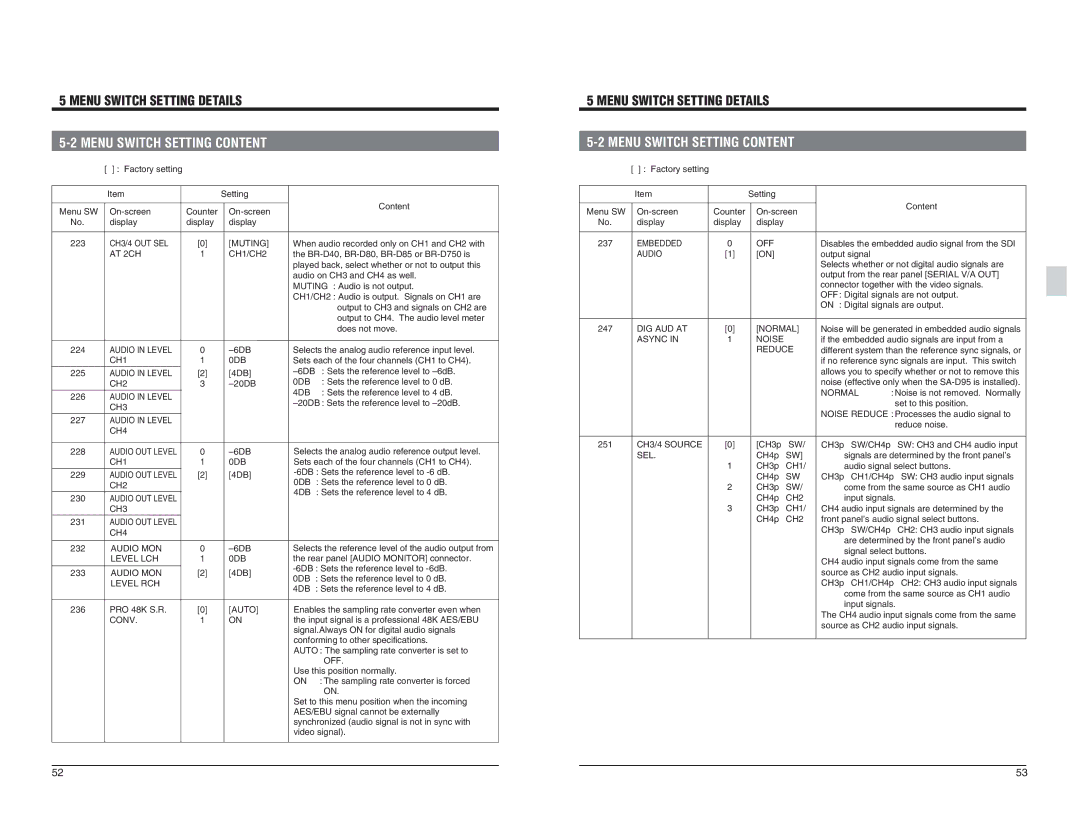
| [ ] : Factory setting |
|
|
| Item |
| Setting |
Menu SW | Counter | ||
No. | display | display | display |
223 | CH3/4 OUT SEL | [0] | [MUTING] |
| AT 2CH | 1 | CH1/CH2 |
Content |
When audio recorded only on CH1 and CH2 with |
the |
played back, select whether or not to output this |
audio on CH3 and CH4 as well. |
MUTING : Audio is not output. |
CH1/CH2 : Audio is output. Signals on CH1 are |
output to CH3 and signals on CH2 are |
output to CH4. The audio level meter |
| |||
| [ ] : Factory setting |
|
|
| Item |
| Setting |
Menu SW | Counter | ||
No. | display | display | display |
237 | EMBEDDED | 0 | OFF |
| AUDIO | [1] | [ON] |
Content
Disables the embedded audio signal from the SDI output signal Selects whether or not digital audio signals are output from the rear panel [SERIAL V/A OUT] connector together with the video signals. OFF : Digital signals are not output. ON : Digital signals are output.
224 | AUDIO IN LEVEL | 0 | |
| CH1 | 1 | 0DB |
225 | AUDIO IN LEVEL | [2] | [4DB] |
| CH2 | 3 | |
226 | AUDIO IN LEVEL |
|
|
| CH3 |
|
|
227 | AUDIO IN LEVEL |
|
|
| CH4 |
|
|
| does not move. |
Selects the analog audio reference input level. | |
Sets each of the four channels (CH1 to CH4). | |
: Sets the reference level to | |
0DB | : Sets the reference level to 0 dB. |
4DB | : Sets the reference level to 4 dB. |
: Sets the reference level to | |
247 | DIG AUD AT | [0] | [NORMAL] |
| ASYNC IN | 1 | NOISE |
|
|
| REDUCE |
Noise will be generated in embedded audio signals | |
if the embedded audio signals are input from a | |
different system than the reference sync signals, or | |
if no reference sync signals are input. This switch | |
allows you to specify whether or not to remove this | |
noise (effective only when the | |
NORMAL | : Noise is not removed. Normally |
| set to this position. |
NOISE REDUCE : Processes the audio signal to | |
| reduce noise. |
228 | AUDIO OUT LEVEL | 0 | |
| CH1 | 1 | 0DB |
229 | AUDIO OUT LEVEL | [2] | [4DB] |
| CH2 |
|
|
230 | AUDIO OUT LEVEL |
|
|
| CH3 |
|
|
231 | AUDIO OUT LEVEL |
|
|
| CH4 |
|
|
232 | AUDIO MON | 0 | |
| LEVEL LCH | 1 | 0DB |
233 | AUDIO MON | [2] | [4DB] |
| LEVEL RCH |
|
|
236 | PRO 48K S.R. | [0] | [AUTO] |
| CONV. | 1 | ON |
Selects the analog audio reference output level. | |
Sets each of the four channels (CH1 to CH4). | |
0DB | : Sets the reference level to 0 dB. |
4DB | : Sets the reference level to 4 dB. |
Selects the reference level of the audio output from | |
the rear panel [AUDIO MONITOR] connector. | |
0DB | : Sets the reference level to 0 dB. |
4DB | : Sets the reference level to 4 dB. |
Enables the sampling rate converter even when | |
the input signal is a professional 48K AES/EBU | |
signal.Always ON for digital audio signals | |
conforming to other specifications. | |
AUTO : The sampling rate converter is set to | |
| OFF. |
Use this position normally. | |
ON | : The sampling rate converter is forced |
| ON. |
Set to this menu position when the incoming | |
AES/EBU signal cannot be externally | |
synchronized (audio signal is not in sync with | |
video signal). | |
251 | CH3/4 SOURCE | [0] | [CH3pSW/ | CH3pSW/CH4pSW: CH3 and CH4 audio input |
| SEL. |
| CH4pSW] | signals are determined by the front panel’s |
|
| 1 | CH3pCH1/ | audio signal select buttons. |
|
|
| CH4pSW | CH3pCH1/CH4pSW: CH3 audio input signals |
|
| 2 | CH3pSW/ | come from the same source as CH1 audio |
|
|
| CH4pCH2 | input signals. |
|
| 3 | CH3pCH1/ | CH4 audio input signals are determined by the |
|
|
| CH4pCH2 | front panel’s audio signal select buttons. |
|
|
|
| CH3pSW/CH4pCH2: CH3 audio input signals |
|
|
|
| are determined by the front panel’s audio |
|
|
|
| signal select buttons. |
|
|
|
| CH4 audio input signals come from the same |
|
|
|
| source as CH2 audio input signals. |
|
|
|
| CH3pCH1/CH4pCH2: CH3 audio input signals |
|
|
|
| come from the same source as CH1 audio |
|
|
|
| input signals. |
|
|
|
| The CH4 audio input signals come from the same |
|
|
|
| source as CH2 audio input signals. |
52 | 53 |