5 MENU SWITCH SETTING DETAILS
5 MENU SWITCH SETTING DETAILS
|
5-2 MENU SWITCH SETTING CONTENT
[ | ] : Factory setting |
|
|
| Item |
| Setting |
Menu SW | Counter | ||
No. | display | display | display |
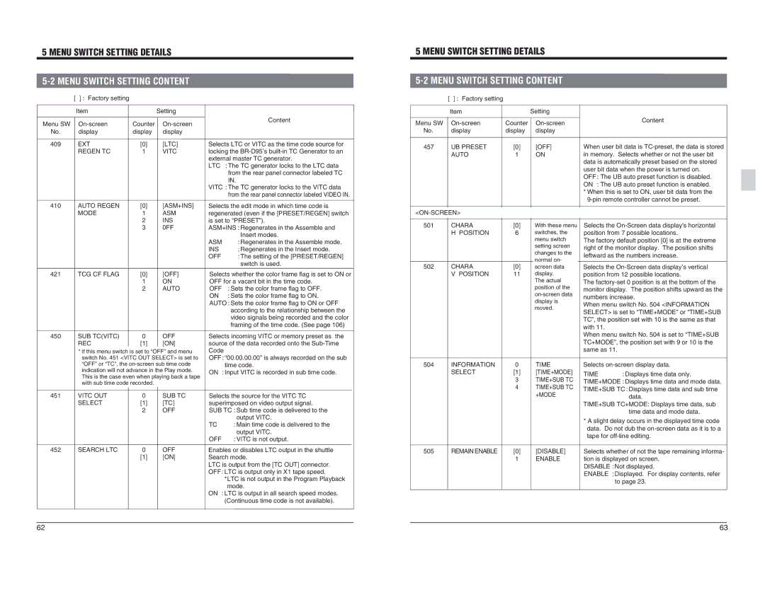
409 | EXT | [0] | [LTC] |
| REGEN TC | 1 | VITC |
Content |
Selects LTC or VITC as the time code source for |
locking the |
external master TC generator. |
LTC : The TC generator locks to the LTC data |
from the rear panel connector labeled TC |
IN. |
VITC : The TC generator locks to the VITC data |
from the rear panel connector labeled VIDEO IN. |
[ | ] : Factory setting |
|
|
| Item |
| Setting |
Menu SW | Counter | ||
No. | display | display | display |
457 | UB PRESET | [0] | [OFF] |
| AUTO | 1 | ON |
Content
When user bit data is
*When this is set to ON, user bit data from the
410 | AUTO REGEN | [0] | [ASM+INS] |
| MODE | 1 | ASM |
|
| 2 | INS |
|
| 3 | 0FF |
421 | TCG CF FLAG | [0] | [OFF] |
|
| 1 | ON |
|
| 2 | AUTO |
450 | SUB TC(VITC) | 0 | OFF |
| REC | [1] | [ON] |
* If this menu switch is set to “OFF” and menu |
switch No. 451 <VITC OUT SELECT> is set to |
Selects the edit mode in which time code is | |
regenerated (even if the [PRESET/REGEN] switch | |
is set to “PRESET”). | |
ASM+INS : Regenerates in the Assemble and | |
| Insert modes. |
ASM | : Regenerates in the Assemble mode. |
INS | : Regenerates in the Insert mode. |
OFF | : The setting of the [PRESET/REGEN] |
| switch is used. |
Selects whether the color frame flag is set to ON or | |
OFF for a vacant bit in the time code. | |
OFF | : Sets the color frame flag to OFF. |
ON | : Sets the color frame flag to ON. |
AUTO : Sets the color frame flag to ON or OFF | |
| according to the relationship between the |
| video signals being recorded and the color |
| framing of the time code. (See page 106) |
Selects incoming VITC or memory preset as the | |
source of the data recorded onto the | |
Code |
|
OFF : “00.00.00.00” is always recorded on the sub | |
|
| |
501 | CHARA | [0] |
| H POSITION | 6 |
502 | CHARA | [0] |
| V POSITION | 11 |
With these menu switches, the menu switch setting screen changes to the normal on- screen data display. The actual position of the
Selects the
Selects the
“OFF” or “TC”, the |
indication will not advance in the Play mode. |
This is the case even when playing back a tape |
with sub time code recorded. |
| time code. |
ON | : Input VITC is recorded in sub time code. |
504 | INFORMATION | 0 | TIME |
| SELECT | [1] | [TIME+MODE] |
|
| 3 | TIME+SUB TC |
|
| 4 | TIME+SUB TC |
Selects | |
TIME | : Displays time data only. |
TIME+MODE : Displays time data and mode data. | |
TIME+SUB TC : Displays time data and sub time | |
451 | VITC OUT | 0 | SUB TC | Selects the source for the VITC TC | |
| SELECT | [1] | [TC] | superimposed on video output signal. | |
|
| 2 | OFF | SUB TC : Sub time code is delivered to the | |
|
|
|
|
| output VITC. |
|
|
|
| TC | : Main time code is delivered to the |
|
|
|
|
| output VITC. |
|
|
|
| OFF | : VITC is not output. |
+MODE |
data. |
TIME+SUB TC+MODE: Displays time data, sub |
time data and mode data. |
*A slight delay occurs in the displayed time code data. Do not dub the
452 | SEARCH LTC | 0 | OFF |
|
| [1] | [ON] |
Enables or disables LTC output in the shuttle Search mode. LTC is output from the [TC OUT] connector. OFF : LTC is output only in X1 tape speed. *LTC is not output in the Program Playback mode. ON : LTC is output in all search speed modes. (Continuous time code is not available).
505 | REMAIN ENABLE | [0] | [DISABLE] |
|
| 1 | ENABLE |
Selects whether of not the tape remaining informa- tion is displayed on screen. DISABLE : Not displayed. ENABLE : Displayed. For display contents, refer to page 23.
62 | 63 |