5 MENU SWITCH SETTING DETAILS |
5 MENU SWITCH SETTING DETAILS
| |||
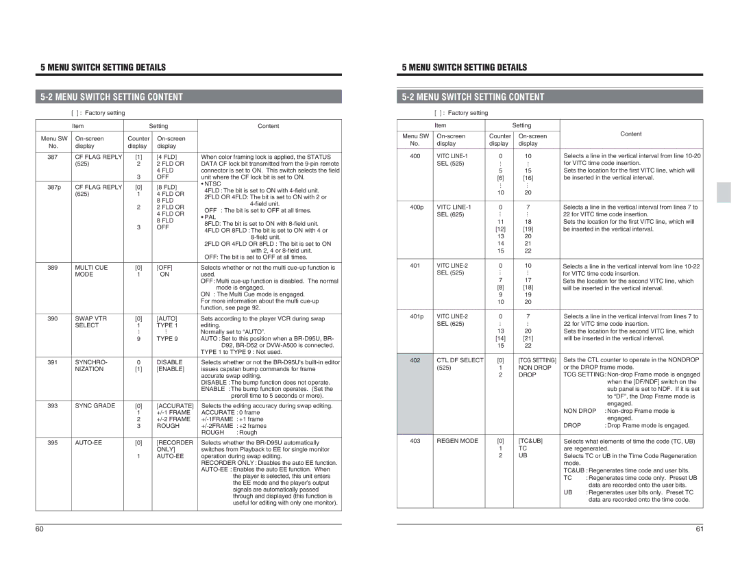
| [ ] : Factory setting |
|
|
| Item |
| Setting |
Menu SW | Counter | ||
No. | display | display | display |
387 | CF FLAG REPLY | [1] | [4 FLD] |
| (525) | 2 | 2 FLD OR |
|
| 3 | 4 FLD |
|
| OFF | |
387p | CF FLAG REPLY | [0] | [8 FLD] |
| (625) | 1 | 4 FLD OR |
|
| 2 | 8 FLD |
|
| 2 FLD OR | |
|
|
| 4 FLD OR |
|
| 3 | 8 FLD |
|
| OFF | |
Content
When color framing lock is applied, the STATUS DATA CF lock bit transmitted from the
•PAL
8FLD: The bit is set to ON with
4FLD OR 8FLD : The bit is set to ON with 4 or |
2FLD OR 4FLD OR 8FLD : The bit is set to ON |
with 2, 4 or |
OFF: The bit is set to OFF at all times. |
| |||
| [ ] : Factory setting |
|
|
| Item |
| Setting |
Menu SW | Counter | ||
No. | display | display | display |
400 | VITC | 0 | 10 |
| SEL (525) | ... | ... |
|
| 5 | 15 |
|
| [6] | [16] |
|
| ... | ... |
|
| 10 | 20 |
400p | VITC | 0 | 7 |
| SEL (625) | ... | ... |
|
| 11 | 18 |
|
| [12] | [19] |
|
| 13 | 20 |
|
| 14 | 21 |
|
| 15 | 22 |
Content
Selects a line in the vertical interval from line
Selects a line in the vertical interval from lines 7 to 22 for VITC time code insertion. Sets the location for the first VITC line, which will be inserted in the vertical interval.
389 | MULTI CUE | [0] | [OFF] |
| MODE | 1 | ON |
Selects whether or not the multi |
used. |
OFF : Multi |
mode is engaged. |
ON : The Multi Cue mode is engaged. |
For more information about the multi |
function, see page 92. |
401 | VITC | 0 | 10 | Selects a line in the vertical interval from line |
| SEL (525) | ... | ... | for VITC time code insertion. |
|
| 7 | 17 | Sets the location for the second VITC line, which |
|
| [8] | [18] | will be inserted in the vertical interval. |
|
| 9 | 19 |
|
|
| 10 | 20 |
|
390 | SWAP VTR | [0] | [AUTO] |
| SELECT | 1 | TYPE 1 |
|
| ... | ... |
|
| 9 | TYPE 9 |
391 | SYNCHRO- | 0 | DISABLE |
| NIZATION | [1] | [ENABLE] |
393 | SYNC GRADE | [0] | [ACCURATE] |
|
| 1 | |
|
| 2 | |
|
| 3 | ROUGH |
Sets according to the player VCR during swap | |
editing. |
|
Normally set to “AUTO”. | |
AUTO : Set to this position when a | |
D92, | |
TYPE 1 to TYPE 9 : Not used. | |
Selects whether or not the | |
issues capstan bump commands for frame | |
accurate swap editing. | |
DISABLE : The bump function does not operate. | |
ENABLE : The bump function operates. (Set the | |
preroll time to 5 seconds or more). | |
Selects the editing accuracy during swap editing. | |
ACCURATE : 0 frame | |
| : +1 frame |
| : +2 frames |
ROUGH | : Rough |
401p
402
VITC
SEL (625)
CTL DF SELECT (525)
0 ... 13 [14] 15
[0] 1 2
7 ... 20 [21] 22
[TCG SETTING] NON DROP DROP
Selects a line in the vertical interval from lines 7 to | |
22 for VITC time code insertion. | |
Sets the location for the second VITC line, which | |
will be inserted in the vertical interval. | |
Sets the CTL counter to operate in the NONDROP | |
or the DROP frame mode. | |
TCG SETTING: | |
| when the [DF/NDF] switch on the |
| sub panel is set to NDF. If it is set |
| to “DF”, the Drop Frame mode is |
| engaged. |
NON DROP | : |
| engaged. |
DROP | : Drop Frame mode is engaged. |
395 |
| [0] | [RECORDER |
|
| 1 | ONLY] |
|
|
Selects whether the |
switches from Playback to EE for single monitor |
operation during swap editing. |
RECORDER ONLY : Disables the auto EE function. |
the player is selected, this unit enters |
the EE mode and the player’s output |
signals are automatically passed |
through and displayed (this function is |
useful for editing with only one monitor). |
403 | REGEN MODE | [0] | [TC&UB] |
|
| 1 | TC |
|
| 2 | UB |
Selects what elements of time the code (TC, UB) | |
are regenerated. | |
Selects TC or UB in the Time Code Regeneration | |
mode. |
|
TC&UB : Regenerates time code and user bits. | |
TC | : Regenerates time code only. Preset UB |
| data are recorded onto the user bits. |
UB | : Regenerates user bits only. Preset TC |
| data are recorded onto the time code. |
60 | 61 |