5 MENU SWITCH SETTING DETAILS |
| ||||
|
|
| |||
Functional | No |
| Names | Description | Reference |
group |
|
|
|
| Page |
SYSTEM | 381 | JOG FEELENG (LOCAL) | Selects jog dial operation response level | ......................................................... 59 | |
| 382 | 9 | PIN | Sets the first digit of the ID code | 59 |
| 383 | 9 | PIN | Sets the second digit of the ID code | 59 |
5 MENU SWITCH SETTING DETAILS |
| |||
|
| |||
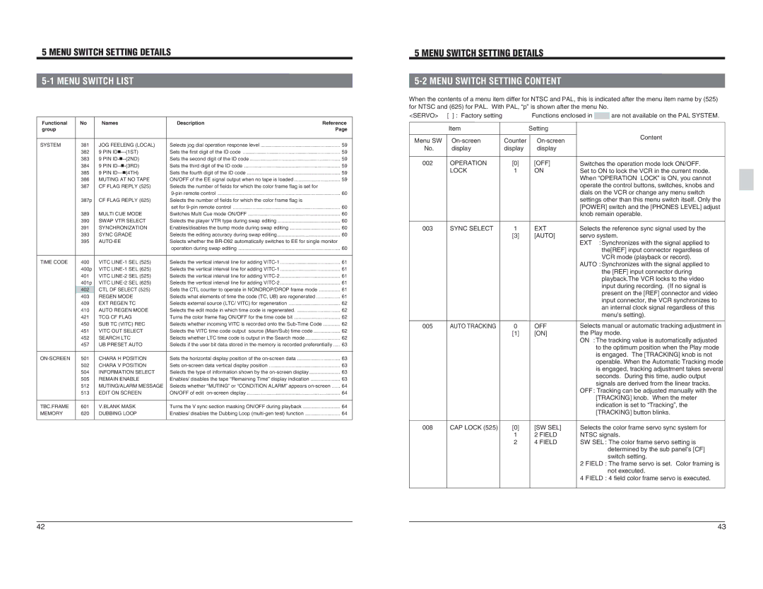
When the contents of a menu item differ for NTSC and PAL, this is indicated after the menu item name by (525) | ||||
for NTSC and (625) for PAL. With PAL, “p” is shown after the menu No. |
| |||
<SERVO> | [ ] : Factory setting |
| Functions enclosed in | are not available on the PAL SYSTEM. |
| Item |
| Setting |
|
Menu SW | Counter | Content | ||
| ||||
No. | display | display | display |
|
| 384 | 9 PIN | Sets the third digit of the ID code | 59 |
| 385 | 9 PIN | Sets the fourth digit of the ID code | 59 |
| 386 | MUTING AT NO TAPE | ON/OFF of the EE signal output when no tape is loaded | 59 |
| 387 | CF FLAG REPLY (525) | Selects the number of fields for which the color frame flag is set for |
|
|
|
| 60 | |
| 387p | CF FLAG REPLY (625) | Selects the number of fields for which the color frame flag is |
|
|
|
| set for | 60 |
| 389 | MULTI CUE MODE | Switches Multi Cue mode ON/OFF | 60 |
| 390 | SWAP VTR SELECT | Selects the player VTR type during swap editing | 60 |
| 391 | SYNCHRONIZATION | Enables/disables the bump mode during swap editing | 60 |
| 393 | SYNC GRADE | Selects the editing accuracy during swap editing | 60 |
| 395 |
| Selects whether the |
|
|
|
| operation during swap editing | 60 |
TIME CODE | 400 | VITC | Selects the vertical interval line for adding | 61 |
| 400p | VITC | Selects the vertical interval line for adding | 61 |
| 401 | VITC | Selects the vertical interval line for adding | 61 |
| 401p | VITC | Selects the vertical interval line for adding | 61 |
| 402 | CTL DF SELECT (525) | Sets the CTL counter to operate in NONDROP/DROP frame mode | 61 |
| 403 | REGEN MODE | Selects what elements of time the code (TC, UB) are regenerated | 61 |
| 409 | EXT REGEN TC | Selects external source (LTC/ VITC) for regeneration | 62 |
| 410 | AUTO REGEN MODE | Selects the edit mode in which time code is regenerated | 62 |
| 421 | TCG CF FLAG | Turns the color frame flag ON/OFF for the time code bit | 62 |
| 450 | SUB TC (VITC) REC | Selects whether incoming VITC is recorded onto the | 62 |
| 451 | VITC OUT SELECT | Selects the VITC time code output source (Main/Sub) time code | 62 |
| 452 | SEARCH LTC | Selects whether LTC time code is output in the Search mode | 62 |
| 457 | UB PRESET AUTO | Selects if the user bit data stored in the memory is recorded preferentially | 63 |
501 | CHARA H POSITION | Sets the horizontal display position of the | 63 | |
| 502 | CHARA V POSITION | Sets | 63 |
| 504 | INFORMATION SELECT | Selects the type of information shown by the | 63 |
| 505 | REMAIN ENABLE | Enables/ disables the tape “Remaining Time” display indication | 63 |
| 512 | MUTING/ALARM MESSAGE | Selects whether “MUTING” or “CONDITION ALARM” appears | 64 |
| 513 | EDIT ON SCREEN | ON/OFF of edit | 64 |
TBC.FRAME | 601 | V.BLANK MASK | Turns the V sync section masking ON/OFF during playback | 64 |
MEMORY | 620 | DUBBING LOOP | Enables/ disables the Dubbing Loop | 64 |
002 | OPERATION | [0] | [OFF] |
| LOCK | 1 | ON |
003 | SYNC SELECT | 1 | EXT |
|
| [3] | [AUTO] |
005 | AUTO TRACKING | 0 | OFF |
|
| [1] | [ON] |
Switches the operation mode lock ON/OFF. | |
Set to ON to lock the VCR in the current mode. | |
When “OPERATION LOCK” is ON, you cannot | |
operate the control buttons, switches, knobs and | |
dials on the VCR or change any menu switch | |
settings other than this menu switch itself. Only the | |
[POWER] switch and the [PHONES LEVEL] adjust | |
knob remain operable. | |
Selects the reference sync signal used by the | |
servo system. | |
EXT | : Synchronizes with the signal applied to |
| the[REF] input connector regardless of |
| VCR mode (playback or record). |
AUTO : Synchronizes with the signal applied to | |
| the [REF] input connector during |
| playback.The VCR locks to the video |
| input during recording. (If no signal is |
| present on the [REF] connector and video |
| input connector, the VCR synchronizes to |
| an internal clock signal regardless of this |
| menu's setting). |
Selects manual or automatic tracking adjustment in | |
the Play mode. | |
ON | : The tracking value is automatically adjusted |
| to the optimum position when the Play mode |
| is engaged. The [TRACKING] knob is not |
| operable. When the Automatic Tracking mode |
| is engaged, tracking adjustment takes several |
| seconds. During this time, audio output |
| signals are derived from the linear tracks. |
OFF : Tracking can be adjusted manually with the | |
| [TRACKING] knob. When the meter |
| indication is set to “Tracking”, the |
| [TRACKING] button blinks. |
008 | CAP LOCK (525) | [0] | [SW SEL] | Selects the color frame servo sync system for | |
|
| 1 | 2 FIELD | NTSC signals. | |
|
| 2 | 4 FIELD | SW SEL : The color frame servo setting is | |
|
|
|
|
| determined by the sub panel’s [CF] |
|
|
|
|
| switch setting. |
|
|
|
| 2 | FIELD : The frame servo is set. Color framing is |
|
|
|
|
| not executed. |
|
|
|
| 4 | FIELD : 4 field color frame servo is executed. |
42 | 43 |