DLA-G150CLU
Can Result
About the installation place
Do not allow any unqualified person to install the unit
About burning-in of the D-ILA device
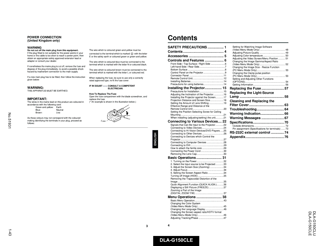
Contents
Controls and Features
Control Panel on the Projector
Bottom Surface
Connector Panel
Remote Control Unit
Installing Batteries
Installing the Projector
Precautions for Installation
Leveling the projector
Adjusting the Inclination of the Projector
Installing the Projector against the Screen
Adjusting the vertical angle of the projector
Projection Distance and Screen Size
Setting the Amount of Lens Shifting
Using as a wireless remote control unit
Effective Range and Distance of the Remote Control Unit
Setting the Position Selecting Screw for Ceiling Mounting
When installing adjusting/setting the unit
Allowable input signals
Connecting to Various Devices
Signals that Can Be Input to the Projector
Video signals
Connecting to Hi-Vision Devices/DVD Players
Connecting to Video Devices
Game device, etc Desktop type
Connecting to Other Devices
Connecting to Devices which Control the Projector
To Control
Connecting to DVI
Connecting to Computer Devices
How to attach the ferrite core
To prevent fire and electric shock, observe the following
Lamp control settings
Basic Operations
Removing the Lens Cap
Projector’s buttons
Turning on the Power Turn on the Main Power switch
Remote control unit
Turning off the Power
Setting the Screen Aspect Ratio
Remote control unit Turning off Image Hide
Removing the Trapezoidal Distortion of the Image
Zooming a Part of the Image
Remote control unit Quick Alignment Function
Displaying a Still Picture Freeze
Submenus in Video Menu Mode
Menu Transition Diagram in No signal Menu Mode
Menu Transition Diagram in Video Menu Mode
Quick Reference Guide for No signal Menu Mode
Factory set value
Menu Transition Diagram in PC Menu Mode
For Video Menu Mode
Quick Reference Guide
Basic Menu Operation
Press the cursor Button 2 or 3 to set Or adjust the value
Quick Reference Guide for PC Menu Mode
Remote control unit Projector
Projector
Changing the Color System Video Menu Mode Only
Video menu mode
PC menu mode
Or Hdtv with the cursor button 5 or ∞
Adjusting Tracking/Phase
Adjust the Screen aspect ratio
Changing the Language Display
Make adjustment with the cursor2 or
Set up for Watching Image Software Video Menu Mode Only
Adjusting Picture Quality
Select the item to be adjusted with the cursor button5 or ∞
Cursor button Or ∞
Adjusting the Video Screen/Menu Position
Adjusting Color temperature
Adjust the color temperature with Cursor button2 or
Select Resize with the cursor button 5 or ∞
Changing the Image Gamma/Aspect Ratio Video Menu Mode Only
Changing the Image Size Resize Function PC Menu Mode Only
Select Gamma or Aspect ratio with the cursor button5 or ∞
Or∞, and press
Setting and Adjusting Other Functions Options
Adjustment item Button
Or∞, and press the Enter button
Projector and the wall outlet
Replacing the Fuse
Getting Information
Select Information with the cursor button5 or ∞
Light-source lamp and lamp use time
Replacing the Light-Source Lamp
Loosen the screws, raise the handle
Reset the lamp use time
Insert the new light-source lamp fully
Inside and fasten the screws
Cleaning and Replacing the Filter Cover
Maintenance
Troubleshooting
When warning indication is shown by the blinking indicators
Operate
Indication Indicator
Action to be taken for warning indication
Lamp Temp
Pressing any button
To cancel this message, press
Power Control Mode LPC
Message is cleared by
GL-M2915SG
Specifications
English Deutsh Français Italiano Español
Pin assignment Specifications for terminals
Outside dimensions
RS-232C external control
Communication Specifications
Command Format
Control command table
For
Appendix
DLA-G150CLEINSTRUCTIONS
EMC
To the following power supply voltage. Use only
Power cord designated by our dealer to ensure Safety
Fire Hazard
Replacing 15the
United Kingdom only
Various Devices
BNC-RCA Conversion plug Deutsh
Front Side / Top Surface / Right Side
Approx m
Ferrite core ⋅ Conversion adapter for Mac for Macintosh
Rear adjustable foot for leveling the projector
Control Panel Projector
Stand by Indicator
Button does not work
Button to obtain a still picture
Gebruike batterijen
PC buttons
Installing the Projector
GL-M2930SZG
English
Remote control unit
Response to color systems systems
640 400 24.83 56.42
To Video Video cable accessory
Hor Pixels Ver Lines KHz PC system PC98
640 350 37.86
VHS VCR
BNC-RCA conversion plug accessory To Video
To Y To PB/B-Y
Game device, etc Hi-Vision devices
Connector Connection cable supplied
To RS-232C connector To Remote terminal To monitor
Cable Supplied
Ferrite core
Basic Operations
Image will be displayed in full
Side of the unit is projected
Comp The image from the Comp Y, R
Pressed PC1 ↔ PC2 ↔ DVI
Quick Alignment Function Quick Align
No.51931
Main menu in No signal Menu Mode
Quick Reference Guide For Video Menu Mode
Options → Refer to
Phase Flickering or dim picture image can be adjusted to
Information → Refer to
Menu returns to the previous menu
Restored
Auto
Adjusting Tracking/Phase
Image adj. submenu appears on the screen
Adjust the color temperature with Cursor button 2 or
Or ∞, and press the Enter button. Then, the All
Video submenu Video submenu Set up 1 submenu
Image enlarged to the full size 1365 ⋅
Españolitaliano Françaisdeutshenglish
Exceeds 2000 hours
Press the Menu button to exit the menu mode
Replacing the Fuse
Cover by loosening screws
Stand by indicator
Projector’s button Turn on the Main Power switch to go
Screw Lamp-replacement opening cover Hide button
Blocked?
With
When warning indication is shown by the blinking indicators
Message Cause Corrective action
Input terminals
Specifications
Optical mechanism system
Electrical system
General
Front
Unit mm
Designates the terminal of the data Dh
21h Control command to the projector
Function Command Asking
Operation Mode parameters
For lens unit GL-M2910G
Español 2002 Victor Company of JAPAN, Limited