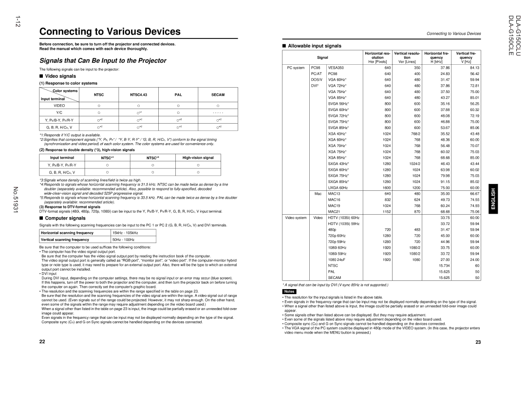
Connecting to Various Devices
Before connection, be sure to turn off the projector and connected devices.
Read the manual which comes with each device thoroughly.
Signals that Can Be Input to the Projector
The following signals can be input to the projector:
■Video signals
(1)Response to color systems
Color systems
Input terminal | NTSC | NTSC4.43 | PAL | SECAM |
| | | |
| | | | |
VIDEO | ‡ | ‡ | ‡ | ‡ |
| | | | |
Y/C | ‡ | 1 | ‡ | - - - - - |
‡* |
Y, P B /B-Y, P R /R-Y | 2 | 2 | 2 | 2 |
‡* | ‡* | ‡* | ‡* |
G, B, R, H/C S , V | 2 | 2 | 2 | 2 |
‡* | ‡* | ‡* | ‡* |
*1:Responds if Y/C output is available. | | | |
*2:Signifies that component signals (“Y, P | B , P R ” / “Y, B-Y, R-Y” / “G, B, R, H/C S , V”) conform to the signal timing |
(synchronization and video period) of each color system. The color systems are used for convenience only. | |
(2)Response to double density (*3), high-vision signals
Input terminal | NTSC* | 4 | NTSC* | 5 | High-vision signal |
| |
| | | | | |
Y, P B /B-Y, P R /R-Y | ‡ | | ‡ | | ‡ |
| | | | | |
G, B, R, H/C S , V | ‡ | | ‡ | | ‡ |
| | | | | |
*3:Signals whose density of scanning lines/field is twice as high.
*4:Responds to signals whose horizontal scanning frequency is 31.5 kHz. NTSC can be made twice as dense by a line doubler (separately available: recommended article). Also, possible to respond to fully-specified, decoded wide-clear-vision signal and decoded 525P progressive signal.
*5:Responds to signals whose horizontal scanning frequency is 33.5 kHz. PAL can be made twice as dense by a line doubler
(separately available: recommended article). | | | | |
(3) Response to DTV-format signals | | | | |
DTV-format signals (480i, 480p, 720p, 1080i) can be input to the Y, P | B /B-Y, P R /R-Y, G, B, R, H/C | S , V input terminal. |
■ Computer signals | | | | |
Signals with the following scanning frequencies can be input to the PC 1 or PC 2 (G, B, R, H/C | S , V) and DVI terminals. |
| | | | |
Horizontal scanning frequency | 15kHz - 105kHz | | | |
| | | | |
Vertical scanning frequency | 50Hz - 100Hz | | | |
| | | | |
Be sure that the computer to be used suffices the following conditions:
• The computer has the video signal output port.
Be sure that the computer has the video signal output port by reading the instruction book of the computer.
The video signal output port is generally called as “RGB port”, “monitor port”, or “video port”. If the computer-monitor hybrid type or note type is used, it may need to prepare for an external output port. Also, there will be the type to which an externa l output port cannot be installed.
• DVI input
During DVI input, depending on the computer settings, there may be no signal input or an error may occur (blue screen).
If this happens, turn off the power to both the projector and the computer, and then turn the projector back on before turning the computer on again. Then correctly set the computer's graphic board.
• The resolution and the scanning frequencies are within the range specified in the table on page 23.
Be sure that the resolution and the scanning frequencies of the video signal are within the range. A video signal out of range cannot be used. (Even signals out of the range could be projected. However, it may not sharp enough. On the other hand, even some of the signals within the range may require adjustment depending on the video board used.)
When a signal other than listed in the table on page 23 is input, the image could be partially erased or an unneeded fold-over image could appear.
Even signals in the frequency range that can be input may not be displayed normally depending on the type of the signal. Composite sync (C S ) and G on Sync signals cannot be handled depending on the devices connected.
22
Connecting to Various Devices
■Allowable input signals
| | | | Horizontal res- | Vertical resolu | - Horizontal fre- | Vertical fre- |
| | Signal | olution | tion | quency | quency |
| | | | Hor [Pixels] | Ver [Lines] | H [kHz] | V [Hz] |
| | | | | | |
PC system | PC98 | VESA350 | 640 | 350 | 37.86 | 84.13 |
| | PC/AT | PC98 | 640 | 400 | 24.83 | 56.42 |
| | DOS/V | VGA 60Hz* | 640 | 480 | 31.47 | 59.94 |
| | DVI* | VGA 72Hz* | 640 | 480 | 37.86 | 72.81 |
| | | VGA 75Hz* | 640 | 480 | 37.50 | 75.00 |
| | | VGA 85Hz* | 640 | 480 | 43.27 | 85.01 |
| | | SVGA 56Hz* | 800 | 600 | 35.16 | 56.25 |
| | | SVGA 60Hz* | 800 | 600 | 37.88 | 60.32 |
| | | SVGA 72Hz* | 800 | 600 | 48.08 | 72.19 |
| | | SVGA 75Hz* | 800 | 600 | 46.88 | 75.00 |
| | | SVGA 85Hz* | 800 | 600 | 53.67 | 85.06 |
| | | XGA 43Hz* | 1024 | 768/2 | 35.52 | 43.48 |
| | | XGA 60Hz* | 1024 | 768 | 48.36 | 60.00 |
| | | XGA 70Hz* | 1024 | 768 | 56.48 | 70.07 |
| | | XGA 75Hz* | 1024 | 768 | 60.02 | 75.03 |
| | | XGA 85Hz* | 1024 | 768 | 68.68 | 85.00 |
| | | SXGA 43Hz* | 1280 | 1024/2 | 46.43 | 43.44 |
| | | SXGA 60Hz* | 1280 | 1024 | 63.98 | 60.02 |
| | | SXGA 75Hz* | 1280 | 1024 | 79.98 | 75.03 |
| | | SXGA 85Hz* | 1280 | 1024 | 91.15 | 85.02 |
| | | UXGA 60Hz | 1600 | 1200 | 75.00 | 60.00 |
| | | | | | | |
| | Mac | MAC13 | 640 | 480 | 35.00 | 66.67 |
| | | MAC16 | 832 | 624 | 49.73 | 74.55 |
| | | MAC19 | 1024 | 768 | 60.24 | 74.93 |
| | | MAC21 | 1152 | 870 | 68.68 | 75.06 |
Video system | | Video | HDTV (1035i) 60Hz | | | 33.75 | 60.00 |
| | | HDTV (1035i) 59Hz | | | 33.72 | 59.94 |
| | | 480p | 720 | 483 | 31.47 | 59.94 |
| | | 720p 60Hz | 1280 | 720 | 45.00 | 60.00 |
| | | 720p 59Hz | 1280 | 720 | 44.96 | 59.94 |
| | | 1080i 60Hz | 1920 | 1080/2 | 33.75 | 60.00 |
| | | 1080i 59Hz | 1920 | 1080/2 | 33.72 | 59.94 |
| | | 1080 24sF | 1920 | 1080 | 27.00 | 24.00 |
| | | NTSC | | | 15.734 | 60 |
| | | PAL | | | 15.625 | 50 |
| | | SECAM | | | 15.625 | 50 |
| | | | | | | |
* A signal that can be input by DVI (V-sync 85Hz is not supported.)
Notes
•The resolution for the input signals is listed in the above table.
•Even signals in the frequency range that can be input may not be displayed normally depending on the type of the signal.
•When a signal other than listed above is input, the image could be partially erased or an unneeded fold-over image could appear.
•Some signals other than listed above can be displayed. But they may require adjustment.
•Even some of the signals listed above may require adjustment depending on the video board used.
•Composite sync (C S ) and G on Sync signals cannot be handled depending on the devices connected.
•The VGA signal of the PC system could be displayed in 480p mode of the VIDEO system. (In this case, the projector enters video menu mode when the MENU button is pressed.)
23